Printed matter defect detection method and device based on artifact elimination

A defect detection and printed matter technology, applied in measurement devices, optical testing of defects/defects, image enhancement, etc., can solve problems such as the effect of affecting printed matter detection, the time-consuming and laborious defect data pictures, and the algorithm not distinguishing between true and false defects.

Active Publication Date: 2020-11-24
HARBIN INST OF TECH SHENZHEN GRADUATE SCHOOL +1
View PDF5 Cites 18 Cited by
  • Summary
  • Abstract
  • Description
  • Claims
  • Application Information

AI Technical Summary

Problems solved by technology

[0003] The traditional method of removing artifacts based on morphological corrosion, when the image is corroded, the algorithm has no ability to distinguish between true and false defects. While removing false contours, some real defects with a relatively small area will also be removed, which affects the effect of printed matter detection.
In addition, the erosion and expansion of image morphology will change some features of the real defect points, such as the defect point area, centroid, shape, etc. These changes have a great adverse effect on the classification and recognition of subsequent defect points.
When the small-sample image defect detection method based on deep learning is applied to an industrial production line, there are very few products with surface defects in printed matter, and it takes time and effort to collect a large amount of defect data and pictures.
In addition, due to the variety of defects in paper prints, it is an unbounded problem; especially for the defects of missing printing, it is difficult to manually label the samples used to train the deep learning model

Method used


Image

  • Printed matter defect detection method and device based on artifact elimination
  • Printed matter defect detection method and device based on artifact elimination
  • Printed matter defect detection method and device based on artifact elimination

Examples


Embodiment Construction

[0043] In order to further describe the technical solution of the present invention in detail, this embodiment is implemented on the premise of the technical solution of the present invention, and provides detailed implementation methods and specific steps.

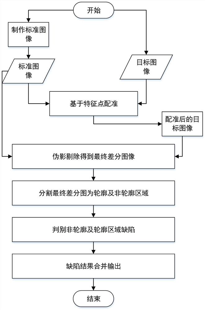
[0044] Such as figure 1 It is a schematic flow chart of an embodiment of the defect detection method of the present invention, and the specific implementation steps are as follows:

[0045] (1) Making a standard image: the embodiment first adopts a CMOS industrial camera with a resolution of 12 million to collect a template image on site, and set the template region ROI for the template image through the web interface template , search area ROI search and clipping region ROI crop , to extract template region ROI template Get the standard image G; set the number of template feature points (feature_num), template rotation angle step (angle_step), template rotation angle upper limit (angle_upper) and lower limit (angle_lo...


PUM


Abstract

The invention discloses a printed matter defect detection method and device based on artifact elimination. The method comprises steps of image positioning and registration, carrying out the positioning and registration of a standard template image and a target image of a to-be-detected printed matter based on a line mod feature point positioning and registration algorithm; target image artifact elimination, respectively dividing the standard image and the target image after positioning and registration into a plurality of sub-blocks with the same size, and eliminating artifacts caused by localdeformation of the target image by using a sub-block neighborhood sliding artifact elimination method; extracting background region defects of the final difference image; extracting a contour of thestandard image and performing mathematical morphology expansion operation to obtain a contour mask, segmenting the final differential image into a contour area and a non-contour area by using a contour mask covering method, extracting and judging defects in the non-contour area and the contour area of the final differential image, and finally integrating, outputting and displaying the defects. Themethod can be used for successfully detecting the defects such as smudginess, incompleteness, ghosting, shifting, scratching and skip printing.

Description

technical field [0001] The invention belongs to the field of defect detection of industrial visual prints, and in particular relates to a method and device for detecting defects of prints based on artifact removal. Background technique [0002] The types of surface defects of printed matter include dirt, incompleteness, ghosting, shifting, scratches, printing missing and color distortion, etc. At present, manual visual inspection is generally used, and experienced workers use naked eye inspection, but long-term naked eye inspection will cause visual fatigue, which is likely to cause missed inspections or misjudgments. In addition, manual visual inspection is inefficient and expensive. In recent years, some detection technologies using image processing and analysis through machine vision have also appeared, but there are also various problems. The technical difficulties in the detection of printed matter defects include: compared with the standard template image, the image co...

Claims


Application Information

Patent Timeline
Patent Type & Authority Applications(China)
IPC IPC(8): G06T7/00G06T7/12G06T7/136G06T7/62G06T7/73G06K9/62G01N21/88
CPCG06T7/001G06T7/12G06T7/136G06T7/62G06T7/73G01N21/8851G06T2207/10004G06T2207/30124G01N2021/8887G06V10/751
Inventor 李东明卢光明范元一郭成昊罗子娟
Owner HARBIN INST OF TECH SHENZHEN GRADUATE SCHOOL
Why Eureka
Try Eureka