
Video monitoring method based on image enhancement

A video monitoring and image enhancement technology, applied in the field of image processing, can solve problems such as difficult to accurately capture details in the furnace that cannot be seen, and achieve the effect of fast speed, simple implementation and high efficiency

Inactive Publication Date: 2020-11-24
WOOTION TECH
View PDF11 Cites 2 Cited by
  • Summary
  • Abstract
  • Description
  • Claims
  • Application Information

AI Technical Summary

Problems solved by technology

[0005] The invention provides a video monitoring method based on image enhancement, which solves the technical problem that it is difficult to accurately capture details in the furnace that cannot be seen under the condition of visible light in the prior art

Method used


Image

  • Video monitoring method based on image enhancement
  • Video monitoring method based on image enhancement
  • Video monitoring method based on image enhancement

Examples


Embodiment 1

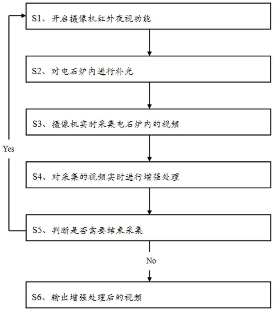
[0038] An embodiment of a video monitoring method based on image enhancement in the present invention is basically as attached figure 1 shown, including steps:

[0039] S1. Turn on the infrared night vision function of the camera;

[0040] S2, supplementing light in the calcium carbide furnace;

[0041] S3, the camera collects the video in the calcium carbide furnace in real time;

[0042] S4. Perform enhanced processing on the collected video in real time;

[0043] S5. According to whether the details in the calcium carbide furnace can be clearly seen in the enhanced video, it is judged whether the collection needs to be terminated: if the details in the calcium carbide furnace can be clearly seen in the enhanced video, the collection is ended; otherwise, if the enhanced processing If the details in the calcium carbide furnace cannot be clearly seen in the subsequent video, continue to collect;

[0044] S6. Outputting the enhanced video.

[0045] The specific implementat...

Embodiment 2

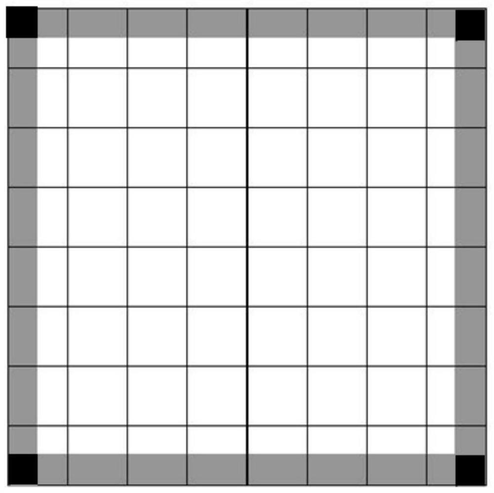
[0072] The only difference from Embodiment 1 is that when clipping the histograms obtained by statistics in each region that exceed the upper limit of 255 so that their amplitudes are lower than the set upper limit, the floating upper limit of the gray value needs to be considered, that is, After adding the floating upper limit on the basis of the set upper limit, the clipping is performed. Specifically, the floating upper limit is the difference between the gray value at the brightest position and the gray value at the darkest position in the image, such as the gray value at the geometric center of the calcium carbide furnace and the gray values ​​at the four corners of the image. value difference.


PUM


Abstract

The invention relates to the technical field of image processing, in particular to a video monitoring method based on image enhancement. The method comprises the following steps: S1, starting an infrared night vision function of a camera; S2, supplementing light into a calcium carbide furnace; S3, acquiring a video in the calcium carbide furnace in real time by a camera; S4, performing enhancementprocessing on the acquired video in real time; S5, judging whether acquisition needs to be ended or not according to a situation that whether details in the calcium carbide furnace can be seen clearly in the enhanced video, and if so, ending the acquisition; otherwise, if details in the calcium carbide furnace cannot be seen clearly in the enhanced video, continuing the acquisition; and S6, outputting the video after enhancement processing. By supplementing light into the calcium carbide furnace and enhancing the acquired video in real time, the technical problem that in-furnace details whichcannot be seen under the condition of visible light are difficult to accurately capture in the prior art is solved.

Description

technical field [0001] The invention relates to the technical field of image processing, in particular to a video monitoring method based on image enhancement. Background technique [0002] Usually, visible light is commonly used to monitor the observation object, such as video surveillance in companies and homes. However, for some special scenes, such as calcium carbide furnaces, strong flames and smoke in the furnace will be generated. If based on visible light video, it is impossible to capture detailed data in the furnace, thus failing to meet the monitoring requirements of calcium carbide furnaces. [0003] In this regard, infrared observation can see images that cannot be seen under visible light conditions. For example, the document CN106851092A discloses a method and device for splicing infrared video. The method includes: extracting the feature points of each image in the infrared video, establishing a matching feature point pair list of the image, obtaining the in...

Claims


Application Information

Patent Timeline
IPC IPC(8): H04N7/18H04N5/33H04N5/235G06T7/11G06T5/40G06T5/00G06T7/62
CPCH04N7/18H04N5/33G06T7/11G06T5/40G06T7/62H04N23/74G06T5/92
Inventor 晁战云袁洪跃罗元泰杨邦敏万钟平赖晗
Owner WOOTION TECH
Learn More