Photocatalytic degradation device for copper slag pollutants and using method thereof

A technology of pollutants and photocatalysis, applied in chemical instruments and methods, chemical/physical/physicochemical processes of energy application, chemical/physical/physicochemical processes, etc., can solve the problem of increasing catalytic time, reducing catalytic efficiency, and sealing performance Poor and other problems, to achieve the effect of fast mixing efficiency, ensure stability, and avoid waste

Inactive Publication Date: 2020-11-27
JIANGXI UNIV OF TECH
View PDF12 Cites 5 Cited by
  • Summary
  • Abstract
  • Description
  • Claims
  • Application Information

AI Technical Summary

Problems solved by technology

[0004] The purpose of the present invention is to solve the problem that the existing photocatalytic degradation device has poor sealing performance during use, which leads to increased catalytic time and reduced catalytic efficiency.

Method used


Image

  • Photocatalytic degradation device for copper slag pollutants and using method thereof
  • Photocatalytic degradation device for copper slag pollutants and using method thereof
  • Photocatalytic degradation device for copper slag pollutants and using method thereof

Examples


Embodiment 1

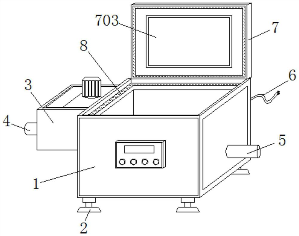
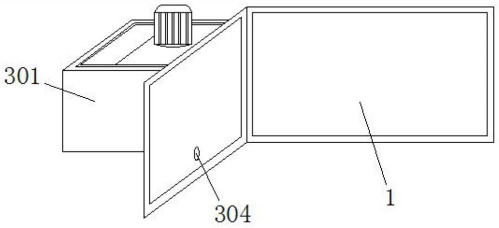
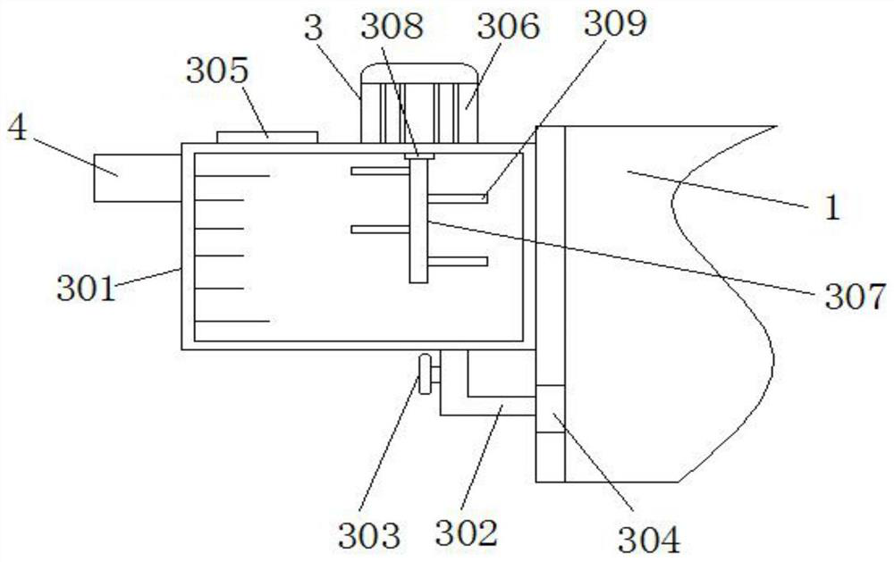
[0051] Please refer to Figure 1 to Figure 6 , a photocatalytic degradation device for copper slag pollutants, including a chassis 1, a stabilizing mechanism 2, a fixed block 201, a threaded column 202, a chassis 203, a first nut 204, a second nut 205, a drug mixing mechanism 3, Dispensing box 301, feeding pipe 302, feeding valve 303, feeding port 304, cover plate 305, motor 306, stirring rod 307, movable shaft 308, blade 309, water inlet 4, water outlet 5, external wiring 6, opening Catalytic mechanism 7, case cover 701, sealing layer 702, catalytic lamp 703, guide groove 704, push switch 705, guide block 706, return spring 707, movable block 708, positioning mechanism 8, place screen cloth 801, side frame 802, The positioning block 803 , the handle 804 , the side plate 805 , the positioning bolt 806 and the positioning groove 807 .

[0052] A stabilizing mechanism 2 is installed at the bottom of the cabinet 1 , and a positioning mechanism 8 is connected inside the cabinet 1...

Embodiment 2

[0064] The present invention also proposes a method for using a photocatalytic degradation device for copper slag pollutants, comprising the following steps:

[0065] Step 1: placing the photocatalytic degradation device and the placing surface after leveling;

[0066] Step 2: Pass the external raw water into the interior of the dispensing box, and then make the ratio according to the water volume;

[0067] Step 3: Put water into the inside of the chassis, and then put the screen with copper slag pollutants into the inside of the chassis for immersion;

[0068] Step 4: Put the lid on the box, turn on the photocatalytic degradation device, and make the catalytic lamp start to work, so as to photocatalytically degrade the copper slag pollutants.

[0069] Specifically, the specific operations of each step in the above method are as follows:

[0070] Step 1: When it is necessary to level the photocatalytic degradation device with the placement surface, the first nut 204 and the ...


PUM


Abstract

The invention relates to a photocatalytic degradation device for copper slag pollutants and a using method thereof. The device comprises a case, a stabilizing mechanism is installed at the bottom endof the case, a positioning mechanism is connected into the case, a chemical mixing mechanism is installed on the surface of the left end of the case, and a water inlet is connected to the surface of the left end of the chemical mixing mechanism. According to the invention, after a placing screen is positioned, an external connecting wire of the case can be connected with an external power supply,and then a case cover is closed; when the case cover is closed, the case cover presses the movable block to shift through a guide block; and when the case cover moves to a certain position, the guideblock makes contact with a pressing switch, then the pressing switch is pressed down, a catalytic lamp installed on the case cover is turned on, and therefore the catalytic lamp can conduct photocatalytic degradation on internal liquid medicine and copper slag pollutants. The photocatalytic degradation device provided by the invention can achieve a good catalytic degradation effect on copper slagpollutants.

Description

technical field [0001] The invention relates to the technical field of photocatalytic degradation equipment for copper slag pollutants, in particular to a photocatalytic degradation device for copper slag pollutants and a use method thereof. Background technique [0002] Photocatalytic degradation reaction refers to the use of highly active free radicals generated by photocatalysts in the reaction system, and then through the process of addition, substitution and electron transfer between free radicals and organic pollutants, all pollutants are degraded into inorganic process. At present, this reaction is widely used in the treatment of copper slag pollutants. [0003] When degrading copper slag pollutants, it is necessary to use a photocatalytic degradation device to perform degradation operations. The existing photocatalytic degradation device for copper slag pollutants can effectively treat copper slag pollutants during use. However, the existing photocatalytic degrada...

Claims


Application Information

Patent Timeline
Patent Type & Authority Applications(China)
IPC IPC(8): B01J19/12B01F15/04B01F7/18
CPCB01J19/123B01J19/0073B01F27/90B01F35/83
Inventor 宋军伟彭小英
Owner JIANGXI UNIV OF TECH
Why Eureka
Try Eureka