
Full-automatic bidirectional chamfering system for end part of steel bar, and working method thereof

A fully automatic, steel bar technology, applied in the field of machinery, can solve the problems of unachieved unilateral leveling, difficult processing, easy jamming of steel bars, etc., to maintain the consistency of chamfering quality, compact device structure connection, The effect of a high degree of automation

Pending Publication Date: 2020-11-27
俊钛金属材料(浙江)有限公司
View PDF1 Cites 3 Cited by
  • Summary
  • Abstract
  • Description
  • Claims
  • Application Information

AI Technical Summary

Problems solved by technology

[0005] 1. The feeding device has poor stability in conveying steel rods to the frame, and cannot realize accurate feeding of steel rods
[0006] 2. The steel rods are easy to form stacks in the feeding device, resulting in the failure of the steel rods to be easily jammed in conveying
[0007] 3. The steel bar is easy to shake in the positioning groove of the frame, with poor stability and poor chamfering effect
[0008] 4. Unilateral leveling is not achieved before chamfering, manual adjustment is required and the processing quality of steel bars varies
[0009] 5. The process continuity of the whole device is poor, the work efficiency is low, the processing is difficult, and the actual operation equipment is difficult to realize

Method used


Image

  • Full-automatic bidirectional chamfering system for end part of steel bar, and working method thereof
  • Full-automatic bidirectional chamfering system for end part of steel bar, and working method thereof
  • Full-automatic bidirectional chamfering system for end part of steel bar, and working method thereof

Examples


Embodiment Construction

[0039] Specific embodiments of the present invention will be further described in detail below. It should be understood that the description of the embodiments of the present invention here is not intended to limit the protection scope of the present invention.

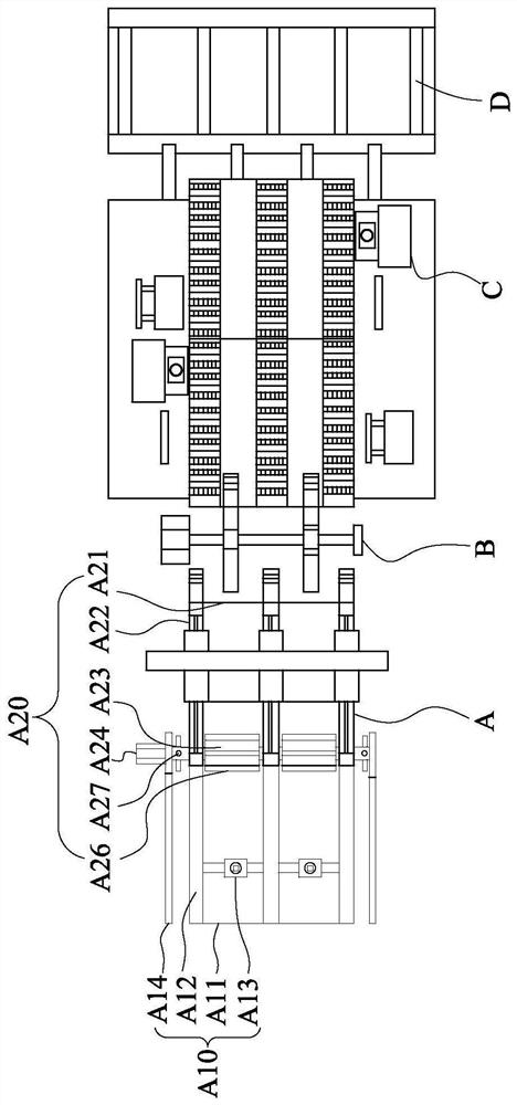
[0040] see Figure 1 to Figure 7, which is a structural schematic diagram of a fully automatic two-way chamfering system for steel bar ends provided by the present invention. A fully automatic two-way chamfering system for steel rod ends, which includes a steel rod feeding mechanism A, a steel rod turning and transferring mechanism B arranged on one side of the steel rod feeding mechanism A, and a steel rod turning and transferring mechanism B arranged on the side of the steel rod feeding mechanism A The steel bar turning and transferring mechanism B is away from the steel bar bidirectional chamfering mechanism C on the side of the steel bar feeding mechanism A, and a steel bar bidirectional chamfering mechanism C is...


PUM


Abstract

A full-automatic bidirectional chamfering system for the end part of a steel bar comprises a steel bar feeding mechanism, a steel bar turnover and transfer mechanism arranged on one side of the steelbar feeding mechanism, a steel bar bidirectional chamfering mechanism arranged on one side, far away from the steel bar feeding mechanism, of the steel bar turnover and transfer mechanism, and a steelbar discharging mechanism arranged on one side, far away from the steel bar turnover and transfer mechanism, of the steel bar bidirectional chamfering mechanism. The steel bar feeding mechanism can transfer the steel bar to the steel bar turnover and transfer mechanism, the steel bar turnover and transfer mechanism transfers the steel bar to the steel bar bidirectional chamfering mechanism, and the steel bar bidirectional chamfering mechanism transfers the steel bar to the steel bar discharging mechanism after finishing machining. The full-automatic bidirectional chamfering system for the endpart of the steel bar is high in automation degree, conveying stability is enhanced, and working efficiency is improved.

Description

technical field [0001] The invention belongs to the technical field of machinery, in particular to a fully automatic two-way chamfering system for steel bar ends. Background technique [0002] At present, in the chamfering process of steel rods, ordinary machine tools and ordinary cutter heads are commonly used for chamfering, which requires manual loading and unloading and the need to turn over the steel rods. This working method is time-consuming, labor-intensive and inefficient. . [0003] For example, Chinese patent literature discloses a stainless steel rod double-ended chamfering device [application number: 201720846478.5], which includes a frame, one side of the frame is provided with a feeding mechanism, the other side is provided with a material receiving mechanism, and It includes chamfering machines respectively arranged at the two ends of the frame, and the two chamfering machines are arranged alternately; several support plates parallel to each other are fixed ...

Claims


Application Information

Patent Timeline
Patent Type & Authority Applications(China)
IPC IPC(8): B23D79/00B23Q7/16
CPCB23D79/00B23Q7/16
Inventor 黄朝辉
Owner 俊钛金属材料(浙江)有限公司
Learn More