Concrete reinforcement frame welding equipment

A technology for concrete reinforcement and welding equipment, applied in welding equipment, welding equipment, auxiliary welding equipment, etc., can solve the problems of moving frames and high labor intensity of construction workers, and achieve the goal of reducing labor intensity, manual operation, and operation difficulty Effect

Active Publication Date: 2020-11-27
无锡鼎尚建设股份有限公司
View PDF7 Cites 4 Cited by
  • Summary
  • Abstract
  • Description
  • Claims
  • Application Information

AI Technical Summary

Problems solved by technology

[0003] Nowadays, construction workers generally place the steel bars in a frame, then move the position to be welded to the bottom of the electric welding equipment, and then manipulate the electric welding equipment to w

Method used


Image

  • Concrete reinforcement frame welding equipment
  • Concrete reinforcement frame welding equipment
  • Concrete reinforcement frame welding equipment

Examples


Embodiment approach 1

[0028] A concrete reinforcement frame welding equipment, such as Figure 1-10As shown, it includes a bottom plate 1, a guide rod 2, a placement frame 3, a first spring 4, a first support plate 5, a second support plate 6, a first support frame 7, a servo motor 8, a first transmission wheel 9, and a transmission belt. 10. Slide bar 11, spot welding assembly 12 and moving assembly 13. Guide rod 2, first support plate 5 and second support plate 6 are installed with bolts on the front and rear sides of the top of bottom plate 1. Guide rod 2 is located on the two first Between the supporting board 5 and the two second supporting boards 6, the two first supporting boards 5 are respectively connected with the two second supporting boards 6, a sliding frame 3 is provided between the two guiding rods 2, and the two guiding rods 2 The first spring 4 is sheathed on the rod 2, the right end of the first spring 4 is connected with the guide rod 2, the left end of the first spring 4 is conn...

Embodiment approach 2

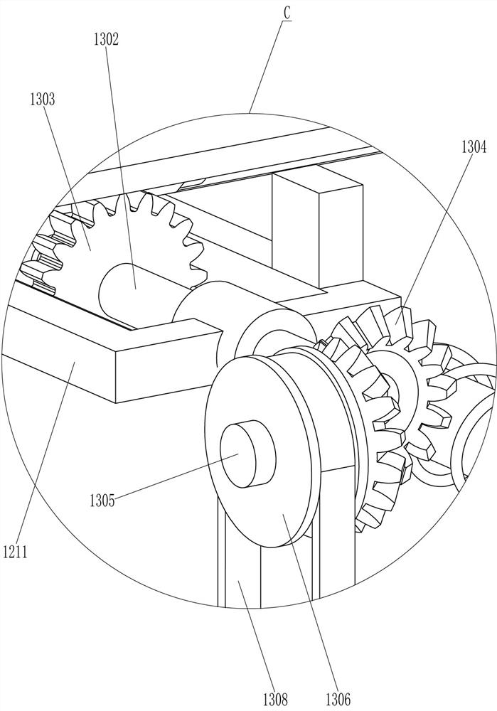
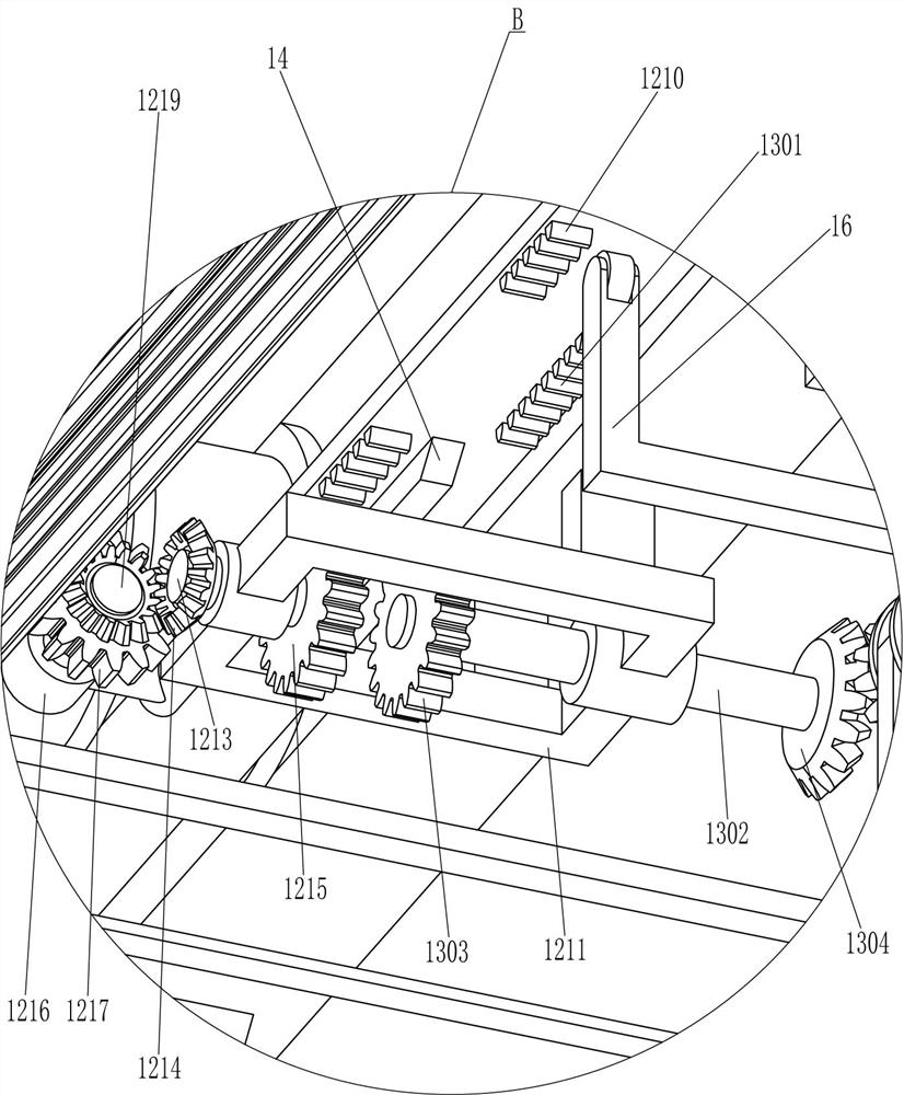
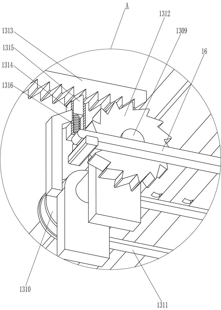
[0035] On the basis of Embodiment 1, such as figure 2 , image 3 , Figure 7 , Figure 9 with Figure 10 As shown, it also includes trapezoidal strip 14, second guide sleeve 15, special-shaped rod 16 and fourth spring 17, two trapezoidal strips 14 are connected to the outside of transmission belt 10, and the second guide sleeve 15 is connected to the right side of the bottom plate 1 top. Two guide sleeves 15 are positioned at the right side of the third bracing frame 1307, and the second guide sleeve 15 is provided with a special-shaped rod 16, and the wedge-shaped rod 1315 and the drive belt 10 are all in contact with the special-shaped rod 16, and the special-shaped rod 16 is covered with a fourth spring 17. The bottom ends of the four springs 17 are connected with the second guide sleeve 15 , and the top ends of the fourth springs 17 are connected with the special-shaped rod 16 .

[0036] When the servo motor 8 rotates clockwise, the first transmission wheel 9 and the ...


PUM


Abstract

The invention relates to welding equipment, in particular to concrete reinforcement frame welding equipment. The concrete reinforcement frame welding equipment can relieve the labor intensity of building workers. The concrete reinforcement frame welding equipment comprises a bottom plate, and the two sides of the top of the bottom plate are in bolt connection with guide rods, first supporting plates and second supporting plates correspondingly; the guide rods are located between the first supporting plates on the two sides and the second supporting plates on the two sides; and the first supporting plates and the second supporting plates are fixedly connected. According to the concrete reinforcement frame welding equipment, rebars can be automatically moved through a moving assembly and welded through a spot welding assembly, manual operation is reduced, and accordingly, the labor intensity of the building workers can be relieved; and a wedge-shaped rod can be pushed to move downwards through a special-shaped rod, ratchets are not stuck by the wedge-shaped rod any more, thus, the building workers do not need to manually pull the wedge-shaped rod downwards, and the operation difficulty is lowered.

Description

technical field [0001] The invention relates to a welding device, in particular to a concrete reinforcement frame welding device. Background technique [0002] Concrete is a building material, with cement as the main cementitious material, mixed with water, sand and stones in proportion, and chemical admixtures and mineral admixtures are added when necessary. After solidification, it has pressure resistance, water resistance, fire resistance, etc. Features, in the pouring process, in order to make the building more stable, it is necessary to set up many steel frames, which are welded by many steel bars. [0003] Nowadays, construction workers generally place the steel bars in a frame, then move the position to be welded to the bottom of the electric welding equipment, and then manipulate the electric welding equipment to weld the steel bars. There are many positions to be welded, so construction workers need to move frequently Frame, but also frequent manipulation of weldin...

Claims


Application Information

Patent Timeline
IPC IPC(8): B23K31/02B23K37/02B23K37/047B23K37/00
CPCB23K31/02B23K37/0252B23K37/047B23K37/00
Inventor 邓美鸾
Owner 无锡鼎尚建设股份有限公司
Why Eureka
Try Eureka