Clamping base for automatically turning over workpiece during milling

A technology for automatic turning of workpieces, applied in metal processing mechanical parts, clamping, manufacturing tools, etc., can solve the problems of reducing processing efficiency, increasing processing time, and unable to automatically complete the turning of workpieces, so as to shorten processing time and increase processing. Quantity and the effect of improving processing efficiency

Inactive Publication Date: 2020-11-27
台州市天枢机械科技有限公司
View PDF0 Cites 4 Cited by
  • Summary
  • Abstract
  • Description
  • Claims
  • Application Information

AI Technical Summary

Problems solved by technology

[0002] At present, with the development of society, CNC milling machine, also known as CNC milling machine, is a milling machine controlled by digital signal of electronic meter. CNC milling machine is an automatic processing equipment developed on the basis of general milling machine. The processing technology of the two is basically the same. , the structure is also somewhat similar. The general CNC milling machine can only realize the automation of milling, and the workpiece needs to be fixed manually. Complete the turning of the workpiece, which will increase the processing time and reduce the processing efficiency

Method used


Image

  • Clamping base for automatically turning over workpiece during milling
  • Clamping base for automatically turning over workpiece during milling
  • Clamping base for automatically turning over workpiece during milling

Examples


Embodiment Construction

[0020] All features disclosed in this specification, or steps in all methods or processes disclosed, may be combined in any manner, except for mutually exclusive features and / or steps.

[0021] Combine below Figure 1-8 The present invention is described in detail, and for convenience of description, the orientations mentioned below are now stipulated as follows: figure 1 The up, down, left, right, front and back directions of the projection relationship itself are the same.

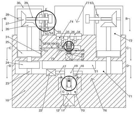
[0022] A clamping base for automatically turning workpieces during milling of the device of the present invention includes a body 10, a power chamber 70 is provided on the lower side of the body 10, and a moving chamber 71 is provided on the upper side of the power chamber 70. The upper side of the chamber 71 is provided with a rotating chamber 73, the upper side of the rotating chamber 73 is provided with a supporting chamber 74, and the upper side of the body 10 is fixed with four circumferentially di...


PUM


Abstract

The invention discloses a clamping base for automatically turning over a workpiece during milling. The clamping base comprises a machine body, wherein a power cavity is formed in the lower side of themachine body; a moving cavity is formed in the upper side of the power cavity; a rotating cavity is formed in the upper side of the moving cavity; a supporting cavity is formed in the upper side of the rotating cavity; four shells which are circumferentially distributed are fixedly arranged on the upper side surface of the machine body; clamping cavities are formed in the machine body and each shell; a clamping device for clamping the workpiece is arranged on the lower side of the machine body; the clamping device comprises a main motor which is fixedly installed on the lower side wall of thepower cavity; the main motor is in power connection with a motor shaft; a universal joint is fixedly arranged on the motor shaft; and a turning-over device for turning over the workpiece is arrangedbetween the shells. According to the clamping base, the machining surface of the workpiece in the machining process can be automatically turned over, the machine does not need to be stopped, the workpiece does not need to be manually taken out and fixed, so that the automation of the whole machining process is realized, the machining time can be shortened, the machining efficiency is improved, andthe machining amount is increased.

Description

technical field [0001] The invention relates to the related field of numerical control milling machines, in particular to a clamping base for automatically turning over workpieces during milling. Background technique [0002] At present, with the development of society, CNC milling machine, also known as CNC milling machine, is a milling machine controlled by digital signal of electronic meter. CNC milling machine is an automatic processing equipment developed on the basis of general milling machine. The processing technology of the two is basically the same. , the structure is also somewhat similar. The general CNC milling machine can only realize the automation of milling, and the workpiece needs to be fixed manually. Complete the turning of the workpiece, which will increase the processing time and reduce the processing efficiency. Contents of the invention [0003] In view of the deficiencies of the above-mentioned technologies, the present invention proposes a clampi...

Claims


Application Information

Patent Timeline
Patent Type & Authority Applications(China)
IPC IPC(8): B23Q3/06B23Q3/04
CPCB23Q3/04B23Q3/06
Inventor 韦爵
Owner 台州市天枢机械科技有限公司
Why Eureka
Try Eureka