
Reciprocating submerged liquid hydrogen pump capable of effectively reducing heat transfer loss

A liquid hydrogen and submersible technology, which is applied in variable capacity pump components, liquid variable capacity machines, components of pumping devices for elastic fluids, etc., can solve the problem of motor submerged liquid, time-consuming, and loss Major problems, to achieve the effect of solving the safety technical problems of the motor power mechanism

Active Publication Date: 2020-11-27
HEFEI GENERAL MACHINERY RES INST +1
View PDF14 Cites 1 Cited by
  • Summary
  • Abstract
  • Description
  • Claims
  • Application Information

AI Technical Summary

Problems solved by technology

Its characteristic is that deep pre-cooling is required before starting the pump, and the preparation work is cumbersome and time-consuming, and BOG (a low-temperature liquid that is pressurized and liquefied below the critical temperature, is difficult to be absolutely insulated from the environment and evaporates after absorbing external heat. Gas) loss is large, it will pollute the air and increase the cost
In LNG storage and transportation, there are also electric centrifugal pumps that are completely submerged in liquid, but because the temperature of liquid hydrogen (-253°C) is much lower than that of LNG (-169°C), the problem of motor submersion cannot be solved, so it needs to be solved urgently

Method used


Image

  • Reciprocating submerged liquid hydrogen pump capable of effectively reducing heat transfer loss
  • Reciprocating submerged liquid hydrogen pump capable of effectively reducing heat transfer loss
  • Reciprocating submerged liquid hydrogen pump capable of effectively reducing heat transfer loss

Examples


Embodiment Construction

[0051] The technical solutions in the embodiments of the present invention will be clearly and completely described below with reference to the accompanying drawings in the embodiments of the present invention. Obviously, the described embodiments are only a part of the embodiments of the present invention, but not all of the embodiments. Based on the embodiments of the present invention, all other embodiments obtained by those of ordinary skill in the art without creative efforts shall fall within the protection scope of the present invention.

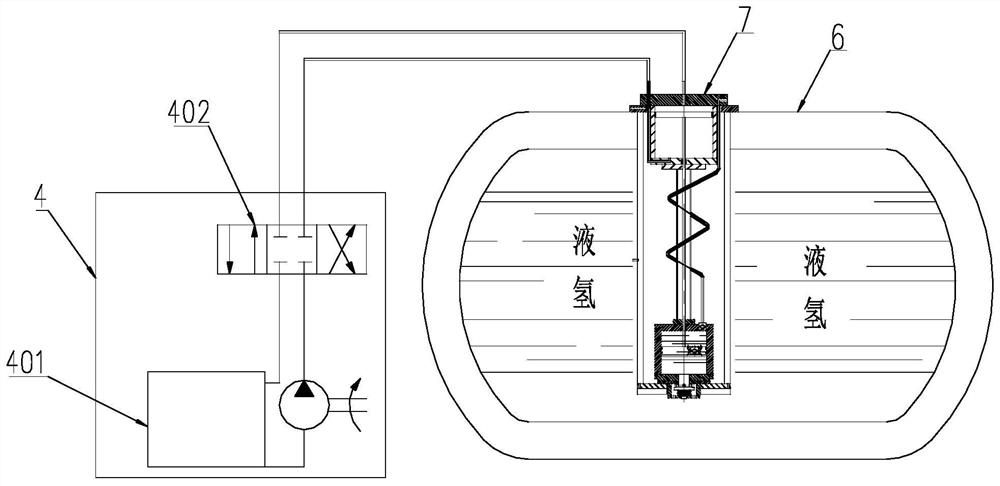
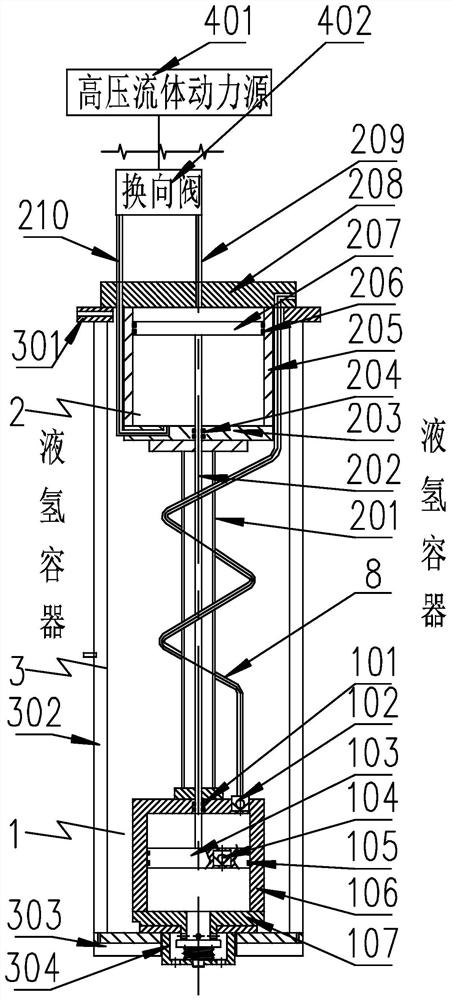
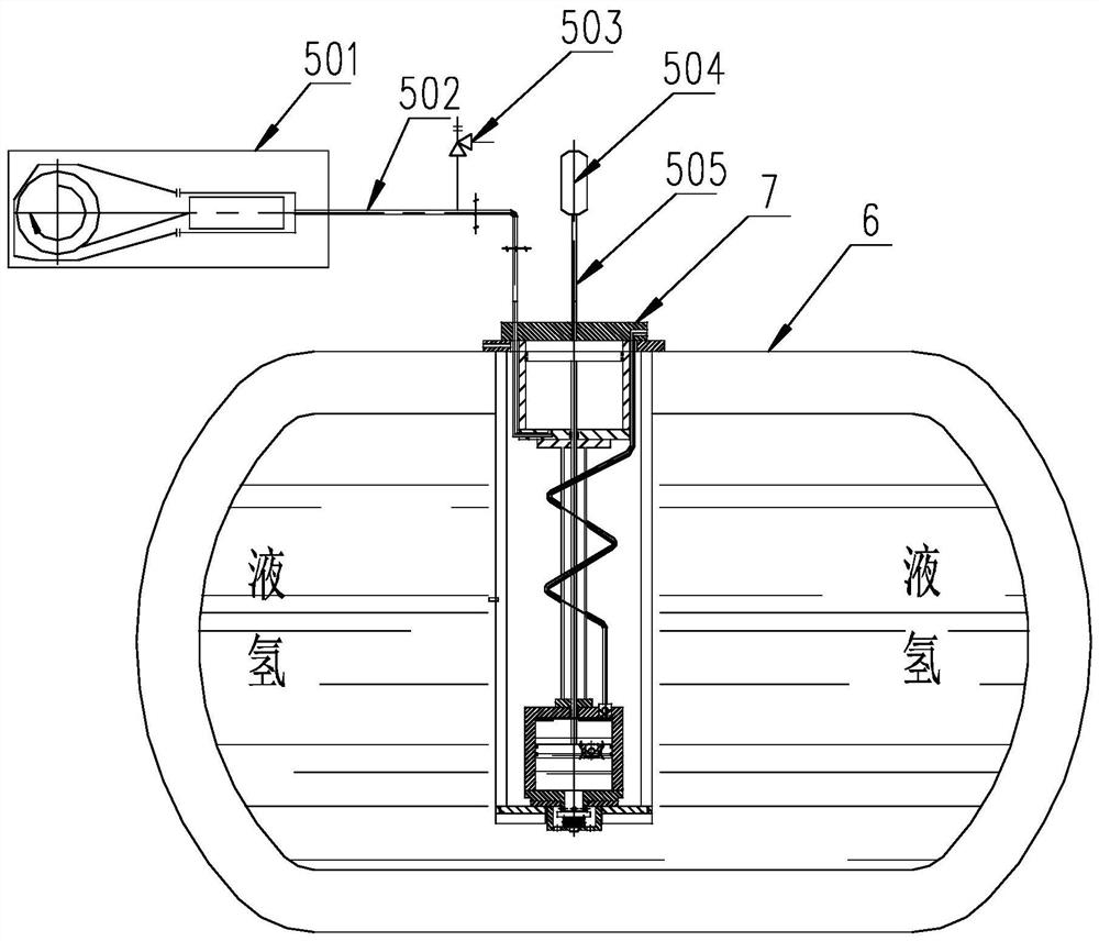
[0052] see Figure 1-5 , In the embodiment of the present invention, a reciprocating submersible liquid hydrogen pump that can effectively reduce heat transfer loss, the reciprocating submersible liquid hydrogen pump includes the following components:

[0053] The reciprocating submersible liquid hydrogen pump includes the following components:

[0054] The isolation part connected with the liquid hydrogen container 6, the isolation ...


PUM


Abstract

The invention discloses a reciprocating submerged liquid hydrogen pump capable of effectively reducing heat transfer loss. The reciprocating submerged liquid hydrogen pump comprises the following components including an isolation part, a pump main body, a cold end part of the pump main body and a power part; the isolation part is connected with a liquid hydrogen container, the pump main body is mounted in the isolation part, and the power part is connected with the cold end part of the pump main body; the cold end part comprises a cold end cylinder body; a cold end piston is arranged in the cold end cylinder body; an isolation valve of the isolation part is arranged on the lower side of the cold end cylinder body; an inlet one-way valve used for communicating an cold end cylinder body upper cavity on the upper side of the cold end piston with a cold end cylinder body lower cavity is arranged on the cold end piston; and an outlet one-way valve used for communicating the cold end cylinder body upper cavity with a liquid hydrogen outlet pipe is arranged at the top of the cold end cylinder body. According to the reciprocating submerged liquid hydrogen pump capable of effectively reducing the heat transfer loss, a pre-cooling step before work is omitted, a normal-temperature piston can be driven through high-pressure fluid, the cold end is driven to reciprocate, the conveying process of liquid hydrogen is completed, the heat transfer speed of a supporting rod is reduced, the heat transfer loss of the liquid hydrogen pump is reduced to be lower, and the possibility is provided for arranging the liquid hydrogen pump on a large-size liquid hydrogen tank.

Description

technical field [0001] The invention relates to the field of liquid hydrogen energy, in particular to a reciprocating submersible liquid hydrogen pump that can effectively reduce heat transfer loss. Background technique [0002] Liquid hydrogen (LH2) is a high-energy, ultra-low temperature liquid clean fuel. Compared with gaseous hydrogen and metal hydride, liquid hydrogen has unparalleled advantages in energy storage density and transportation cost, and has a broad development space. China has also issued a number of relevant policies to support the hydrogen energy industry. The liquid hydrogen pump used for liquid hydrogen transportation is one of the important equipment in the liquid hydrogen industry. [0003] At present, the unloading and transportation of liquid hydrogen basically adopts the method of pressurized extrusion. The container design requires high requirements, the output pressure is low, and the high temperature pressurized gas may cause the risk of thermo...

Claims


Application Information

Patent Timeline
Patent Type & Authority Applications(China)
IPC IPC(8): F04B15/08F04B9/103F04B23/02F04B53/10F04B53/12F04B53/14F04B53/16F04B13/00F04B51/00
CPCF04B15/08F04B9/103F04B23/02F04B53/10F04B53/1032F04B53/12F04B53/14F04B53/143F04B53/16F04B53/162F04B13/00F04B51/00F04B2015/0822
Inventor 王永强陈正文刘海山文宏刚鲁飞韩彩红庞雷苏吉鑫曲玉栋韦志超
Owner HEFEI GENERAL MACHINERY RES INST
Learn More