Multilayer underground water level observation device for hydrogeological hole

A water level observation and geological hole technology, applied in the direction of measuring devices, sampling devices, lubrication indicating devices, etc., can solve the problems of slow sampling process, cumbersome and inconvenient steps of extracting liquid, achieve air pressure balance, and facilitate sampling and pumping detection Effect

Inactive Publication Date: 2020-11-27
肖华
View PDF0 Cites 4 Cited by
  • Summary
  • Abstract
  • Description
  • Claims
  • Application Information

AI Technical Summary

Problems solved by technology

[0003] At present, the water level observation of multi-layer groundwater is to directly lower the sampling device into the groundwater for sampling. Due to the direct container sampling method, the sampling process is relatively slow, and the container needs to be inspected before it is raised to the ground for testing after sampling. It is very inconvenient to extract the liquid after the container is sealed. Therefore, a multi-layer groundwater level observation device for hydrogeological holes is proposed to facilitate the sampling and detection of groundwater.

Method used


Image

  • Multilayer underground water level observation device for hydrogeological hole
  • Multilayer underground water level observation device for hydrogeological hole
  • Multilayer underground water level observation device for hydrogeological hole

Examples


Embodiment 1

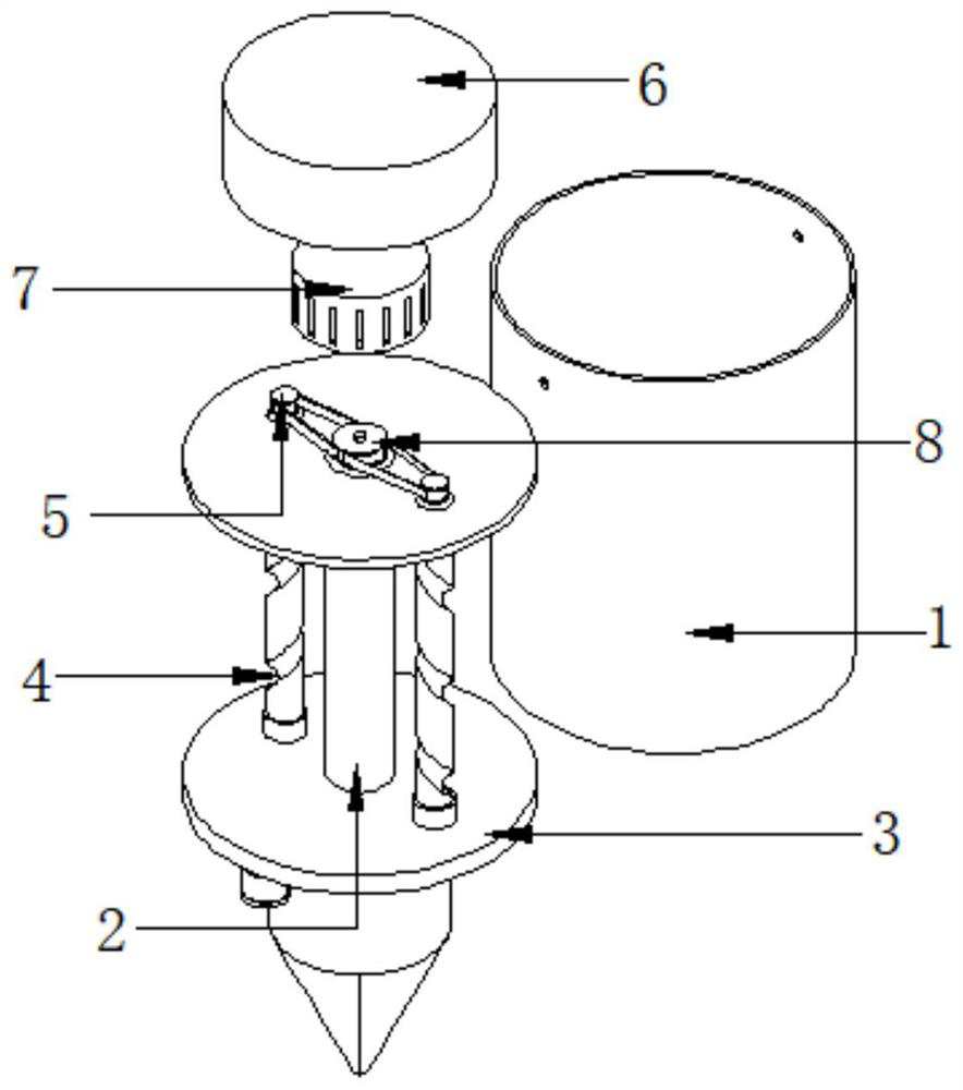
[0026] refer to Figure 1-3 , a multi-layer groundwater level observation device for hydrogeological holes, comprising a liquid storage cylinder 1, a central shaft 2 connected by bolts between the inner walls on both sides of the liquid storage cylinder 1, and a push-pull plate 3 slidingly connected to the outer wall of the central shaft 2, A sealing gasket is installed between the push-pull plate 3 and the central shaft 2, and the inner wall of the bottom of the liquid storage cylinder 1 is connected with two screw screws 4 through bearing rotation, and the other ends of the two screw screws 4 pass through the upper surface of the liquid storage cylinder 1. The side cylinder wall is connected with the secondary wheel disc 5 by bolts, and the push-pull disc 3 is provided with two threaded holes, and the inner wall of the threaded holes is connected with the outer wall of the lead screw 4 in rotation, and the upper outer wall of the liquid storage cylinder 1 is connected with a ...

Embodiment 2

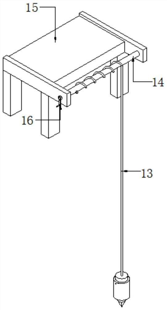
[0030] refer to Figure 4 , a multi-layer groundwater level observation device for hydrogeological holes. Compared with Embodiment 1, the other end of the rope-wrapping rod 14 passes through the side box wall of the console 15 and is connected with a first gear 17 by bolts. And one side outer wall of operating platform 15 is connected with second electric motor 18 by bolt, and the output shaft of second electric motor 18 is connected with short shaft by coupling, and the other end of short shaft is connected with second gear 19 by bolt, and the second The gear 19 is meshed with the first gear 17 through tooth grooves.

[0031] Working principle: when in use, the second motor 18 drives the second gear 19 to rotate, and the second red wheel 19 meshes with the first gear 17 to drive the rope winding rod 14 to retract and retract the pull rope 13, thereby controlling the lifting of the liquid storage cylinder 1 , using motors instead of labor, saving people's physical exertion an...


PUM


Abstract

The invention discloses a multilayer underground water level observation device for a hydrogeological hole. The multilayer underground water level observation device comprises a liquid storage barrel,wherein a middle shaft is fixedly connected between the inner walls of the two sides of the liquid storage barrel; the outer wall of the middle shaft is slidably connected with a push-pull disc; a sealing gasket is arranged between the push-pull disc and the middle shaft; two lead screws are movably connected to the inner wall of the bottom part of the liquid storage barrel; the other ends of thetwo lead screws penetrate through the upper side barrel wall of the liquid storage barrel to be fixedly connected with secondary wheel discs; two threaded holes are formed in the push-pull disc; theinner walls of the threaded holes are movably connected with the outer walls of the lead screws; a motor box is fixedly connected to the outer wall of the upper side of the liquid storage barrel; anda first motor is fixedly connected to the inner wall of the motor box. The multilayer underground water level observation device can perform water absorption and water outlet operation on undergroundwater, facilitates underground water sampling and later water pumping detection, solves the problem that a water body is difficult to take out after sampling, improves the underground water level observation efficiency, can use a motor to replace manpower, and reduces the working intensity.

Description

technical field [0001] The invention relates to the technical field of hydrogeology, in particular to a multi-layer groundwater level observation device for hydrogeological holes. Background technique [0002] The content of water level observation includes river bed changes, flow potential, flow direction, flood diversion, ice conditions, aquatic plants, waves, wind direction, wind force, water surface relief, water temperature and other factors that affect water level changes. When necessary, the slope of the water surface is also measured. [0003] At present, the water level observation of multi-layer groundwater is to directly lower the sampling device into the groundwater for sampling. Since the direct container sampling method is adopted, the sampling process is relatively slow, and the container needs to be inspected before it is raised to the ground for testing after sampling. It is very inconvenient to extract the liquid after the container is sealed. Therefore, a ...

Claims


Application Information

Patent Timeline
Patent Type & Authority Applications(China)
IPC IPC(8): G01N1/14G01F23/00
CPCG01F23/0023G01N1/14
Inventor 肖华王博伦朱宁
Owner 肖华
Why Eureka
Try Eureka