Unit sliding pressure control optimization method and system based on thermoelectric load condition

An optimization method and electric load technology, applied in general control systems, control/regulation systems, adaptive control, etc., can solve problems such as unusable, reduced unit economy, and unsuitable heat and power cogeneration units

Active Publication Date: 2020-11-27
浙江浙能绍兴滨海热电有限责任公司 +1
View PDF7 Cites 3 Cited by
  • Summary
  • Abstract
  • Description
  • Claims
  • Application Information

AI Technical Summary

Problems solved by technology

Before and after the change of heating and extraction steam volume, there is a large gap in the optimal main steam pressure corresponding to the same electrical load. Using the original sliding pressure curve to control the main steam pressure will cause obvious deviations, which will lead to economical failure of the unit. decline, so the original sliding pressure operation curve

Method used


Image

  • Unit sliding pressure control optimization method and system based on thermoelectric load condition
  • Unit sliding pressure control optimization method and system based on thermoelectric load condition
  • Unit sliding pressure control optimization method and system based on thermoelectric load condition

Examples


Embodiment 1

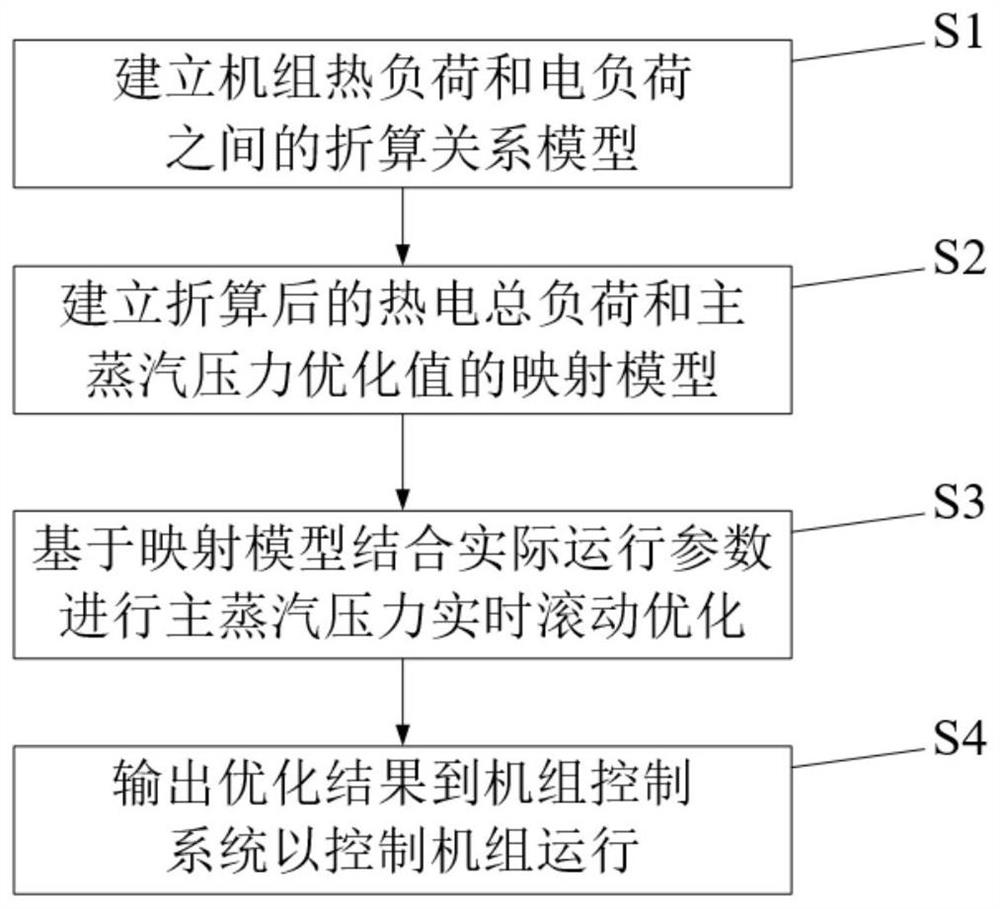
[0114] A real-time optimization method for unit sliding pressure control strategy based on thermal and electrical load conditions, taking a 300MW cogeneration unit in a power plant as an example, includes the following steps:

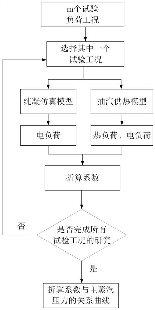
[0115] Step S1, as attached image 3 As shown in the flow chart, the conversion relationship model of unit thermal load converted into electrical load under different loads is established.

[0116] S11, from the effective operating load range of the steam turbine (30%-100%), select a load every 5%, and select the working conditions of 30%, 35%, 40%, ..., 95%, 100% load as the test Load, the corresponding electric load is 90MW, 105MW, ..., 300MW.

[0117] S12, take the test condition of a load in S11, denoted as condition 0, and use the heat balance simulation software of the thermal system to establish a simulation model of the pure condensing power generation condition under this load.

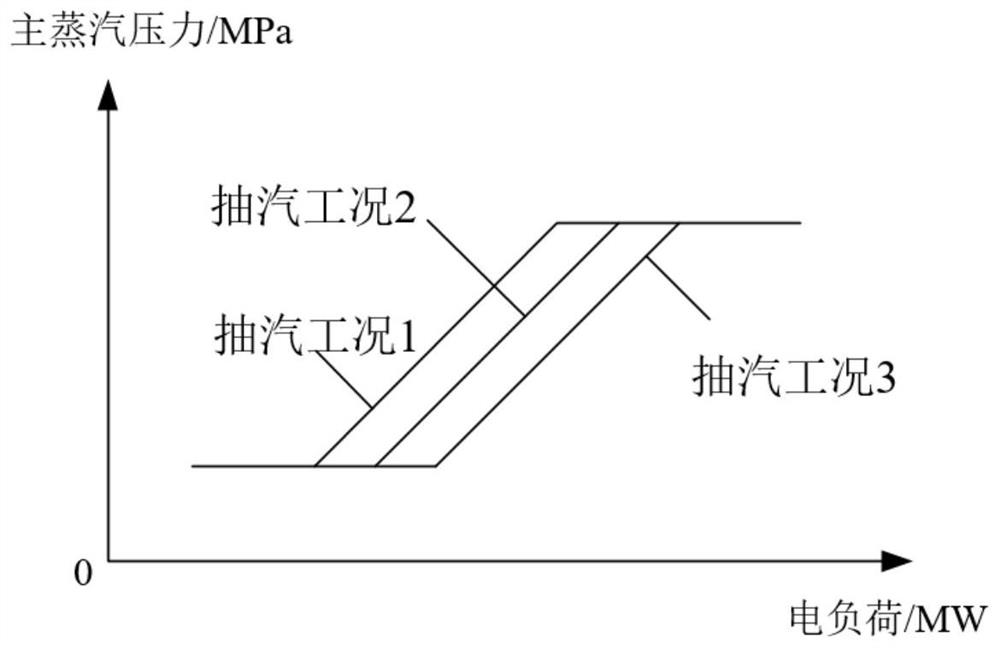
[0118] S13, the 300MW unit shown in this embodiment has three s...

Embodiment 2

[0160] On the basis of the above-mentioned embodiment 1, this embodiment also provides a system for optimizing the sliding pressure control of the unit based on thermal and electrical load conditions, including:

[0161] The input module is used to obtain the real-time operation data of the cogeneration unit;

[0162] The constraint module is used to limit the range of independent variables of the algorithm in the optimization module and improve the efficiency of optimization according to the characteristics of the heating network and power grid dispatching, as well as the heat balance relationship during the operation of the unit. The constraint module includes: real-time The main steam pressure range constraint module of main steam parameters, the thermoelectric load range constraint module based on the dispatching characteristics of the heating network and power grid, and the range constraint module of other independent variables based on mass conservation and heat balance r...


PUM


Abstract

The invention discloses a unit sliding pressure control optimization method and system based on a thermoelectric load condition. The method comprises the steps of S1, establishing a conversion relation model for converting a unit thermal load into an electric load; S2, establishing a mapping model between the thermoelectric load and the main steam pressure optimization value; S3, performing main steam pressure real-time rolling optimization based on the mapping model in combination with actual operation parameters; and S4, outputting an optimization result to a unit control system to control the operation of the unit. According to the unit sliding pressure control optimization method and system based on the thermoelectric load condition, the heat supply amount is taken into consideration,sliding pressure operation strategies of multiple variables such as the thermoelectric load and main steam parameters are comprehensively considered, and thus real-time optimization is conducted.

Description

technical field [0001] The invention relates to a method and system for optimizing sliding pressure control of a unit based on thermoelectric load conditions, and belongs to the technical field of intelligent operation of thermal power generating units. Background technique [0002] At present, with the development of new energy power generation technology, due to the influence of power grid peak regulation, thermal power generating units need to be in variable load operation for a long time, so most of the large thermal power generating units in my country adopt sliding pressure operation to cope with power consumption. Changes in load demand. At the same time, my country has vigorously developed cogeneration units, combining the two energy industries of power supply and heating, realizing cascade utilization of energy, and improving energy utilization and economy. [0003] When the unit is running under sliding pressure, each load condition has a corresponding main steam p...

Claims


Application Information

Patent Timeline
IPC IPC(8): G05B13/04F01K17/02F01D21/00
CPCG05B13/042F01K17/02F01D21/00
Inventor 洪方驰孙海龙严小华任庆周懿
Owner 浙江浙能绍兴滨海热电有限责任公司
Why Eureka
Try Eureka