Alkali liquor oxidation regeneration tail gas cleaning treatment and reutilization method and system

A technology for cleaning exhaust gas and lye, which is applied in gas treatment, chemical instruments and methods, separation methods, etc., to avoid the problem of furnace flue gas emission, reduce factory air volume, and save stainless steel pipelines.

Inactive Publication Date: 2020-12-01
SINOPEC ENG +1
View PDF9 Cites 2 Cited by
  • Summary
  • Abstract
  • Description
  • Claims
  • Application Information

AI Technical Summary

Problems solved by technology

The methods in the above-mentioned patent documents only desu

Method used


Image

  • Alkali liquor oxidation regeneration tail gas cleaning treatment and reutilization method and system
  • Alkali liquor oxidation regeneration tail gas cleaning treatment and reutilization method and system

Examples


Embodiment approach

[0046] According to a preferred embodiment of the present invention, a method for cleaning and reusing alkali liquor oxidation regeneration tail gas, the method comprises the following steps:

[0047] ① The tail gas from the alkaline oxidation regeneration tower passes through the adsorption tank A equipped with adsorbent from bottom to top to remove the N 2 、H 2 O and hydrocarbons to obtain oxygen enriched gas;

[0048] ② After the oxygen-enriched gas is settled and separated from the liquid by the oxygen-enriched gas liquid separation tank, it is boosted by the booster and sent to the gas cooler for cooling;

[0049] ③The cooled oxygen enriched gas is mixed with the external factory air in the mixer to obtain the mixed gas;

[0050] 4. the mixed gas returns to the air inlet of the lower part of the lye oxidation regeneration tower through the online analyzer;

[0051] ⑤ When the adsorption of the adsorbent in the adsorption tank A reaches saturation, switch the tail gas o...

Embodiment

[0072] This embodiment is used to illustrate the method and system of the present invention for cleaning, treating and reusing tail gas from oxidation and regeneration of alkali solution.

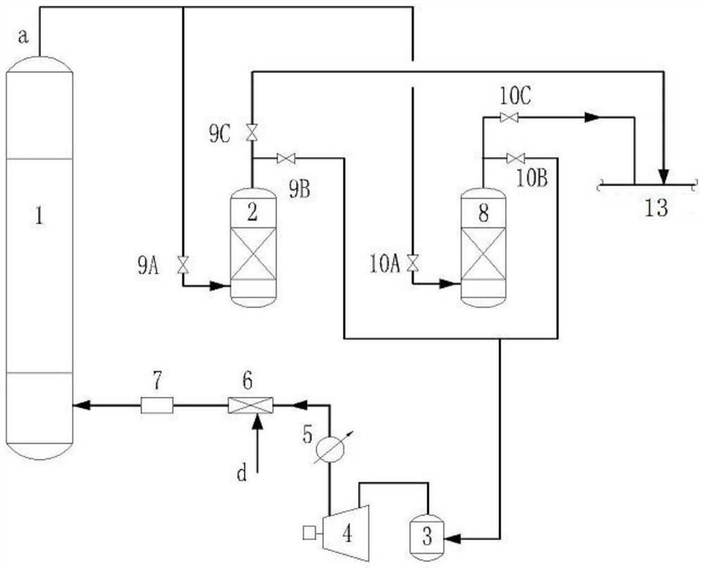
[0073] Such as figure 1 As shown, the present invention provides a kind of lye oxidation regeneration tail gas cleaning treatment and reutilization system, and this system comprises lye oxidation regeneration tower 1, adsorption tank A 2, adsorption tank B 8, oxygen enrichment gas separation tank 3, Turbocharger 4, gas cooler 5, mixer 6 and online analyzer 7;

[0074] The gas outlet of the lye oxidation regeneration tower 1 is communicated with the gas inlet of the adsorption tank A2 and the adsorption tank B8 respectively, and the gas outlet of the alkali lye oxidation regeneration tower 1 is connected with the gas inlet of the adsorption tank A2. The first switching valve α9A, the gas outlet of the lye oxidation regeneration tower 1 and the connecting pipeline of the gas inlet of the ads...


PUM


Abstract

The invention relates to the field of petrochemical gas treatment, and discloses an alkali liquor oxidation regeneration tail gas cleaning treatment and reutilization method and system. The method comprises the steps that a, tail gas of an alkali liquor oxidation regeneration tower passes through an adsorption tank containing an adsorbent from bottom to top, N2, H2O and hydrocarbon in the tail gasare removed, and oxygen extraction concentrated gas is obtained; b, the oxygen-extracted concentrated gas is subjected to settling separation by an oxygen-extracted concentrated gas liquid separationtank to obtain liquid, and the liquid is boosted by a supercharger and sent to a gas cooler for cooling; c, the cooled oxygen extraction concentrated gas is mixed with external factory air in a mixerto obtain mixed gas; d, the mixed gas is returned to an air inlet in the lower part of the alkali liquor oxidation regeneration tower through an on-line analyzer; and e, when the adsorption of the adsorbent in the adsorption tank is saturated, the adsorption tank is desorbed, and desorbed gas is sent to a gas cabinet gas collection header pipe. By adopting the method and the system, the situationthat alkali liquor oxidation regeneration tail gas treatment seriously depends on combustion treatment of an incinerator or a heating furnace can be changed, and clean production and flexible arrangement are realized.

Description

technical field [0001] The invention relates to the field of petrochemical gas treatment, in particular to a method for cleaning and reusing tail gas from oxidation and regeneration of alkali liquor, and a system for cleaning and recycling tail gas from oxidation and regeneration of alkali liquor. Background technique [0002] In the process of liquefied gas sweetening and gasoline sweetening, lye is used as an extraction agent to extract mercaptan in liquefied gas or gasoline into the lye, and then send the lye to the lye oxidation regeneration tower for oxidation Regeneration, the regenerated lye can be recycled, which will greatly reduce the discharge of spent caustic soda. The oxidative regeneration of lye requires the consumption of O 2 And catalyzer, excessive factory air is passed into the lye oxidation regeneration tower, and under the action of the catalyst, sodium mercaptide in the lye and O in the factory air 2 A reaction occurs that regenerates the lye. The re...

Claims


Application Information

Patent Timeline
IPC IPC(8): B01D53/04
CPCB01D53/04B01D2257/702B01D2257/80B01D2257/102
Inventor 张竹梅李出和
Owner SINOPEC ENG
Why Eureka
Try Eureka