Supercharge Your Innovation With Domain-Expert AI Agents!

Tower crane turntable support welding method

A welding method and tower crane technology, applied in welding equipment, welding equipment, auxiliary welding equipment, etc., can solve the problems of large overall structure of supports, low safety, and difficulty in ensuring accuracy, so as to improve position accuracy and ensure welding Accuracy, reducing the effect of welding difficulty

Active Publication Date: 2020-12-01
HUNAN JOINFRONT WELDING TECH
View PDF11 Cites 1 Cited by
  • Summary
  • Abstract
  • Description
  • Claims
  • Application Information

AI Technical Summary

Problems solved by technology

[0007] In the process flow of this traditional welding method, it is difficult to guarantee the position accuracy of each part when the overall frame structure is assembled and the position accuracy during the welding process, which increases the difficulty of welding and is not conducive to the automation of the welding process
Afterwards, the overall frame structure is transported and removed. Since the overall structure of the support of the tower crane turret is large, it needs to be transported by crane. When welding with the outrigger components, it is also necessary to use the crane to turn the edge, which requires a lot of manpower and material resources. Huge and low security
Furthermore, due to the high precision requirements for the hole position of the outrigger assembly, it is difficult to guarantee the accuracy of this welding process, and it is also difficult to control the welding deformation. Therefore, it is difficult to use welding robots for welding, and manual welding is often required, which is highly dependent on the staff. and difficult to guarantee security

Method used


Image

  • Tower crane turntable support welding method
  • Tower crane turntable support welding method
  • Tower crane turntable support welding method

Examples


Embodiment 1

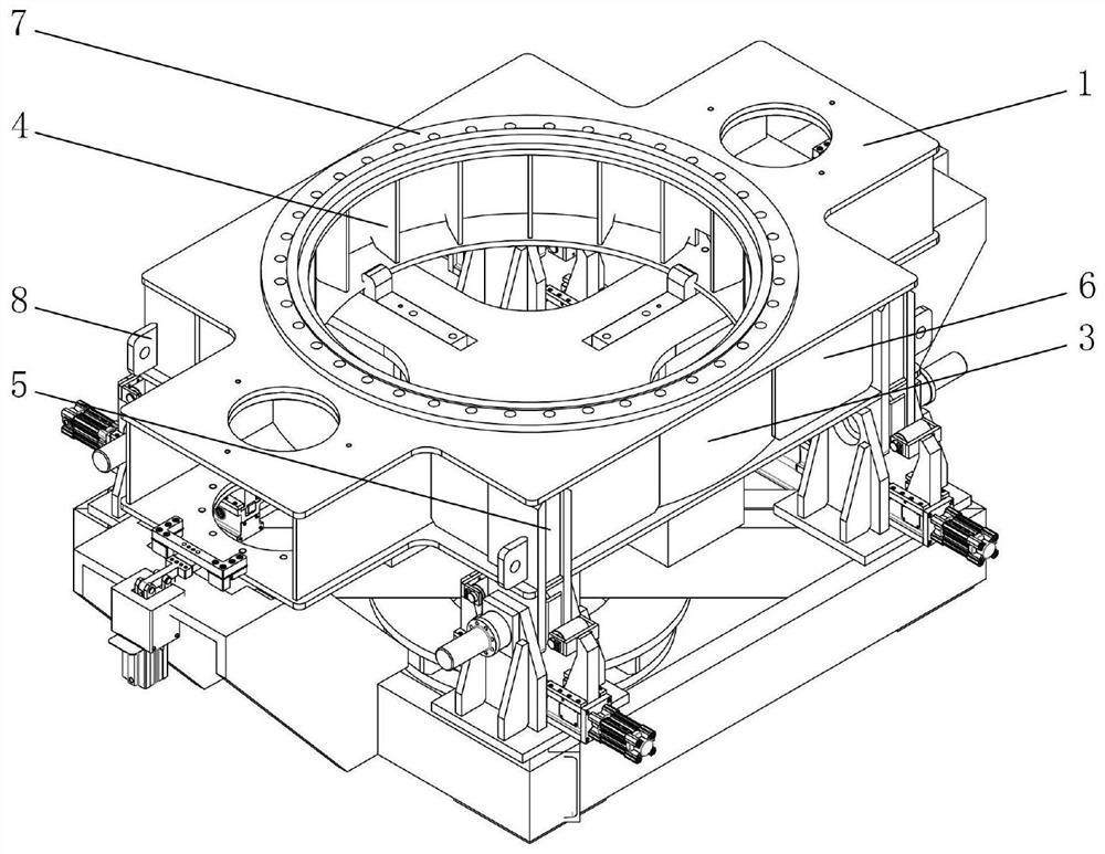
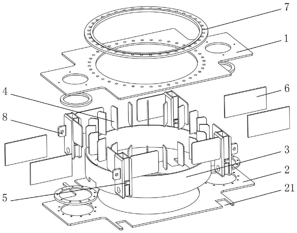
[0034] Such as figure 1 and figure 2 As shown, the welding method of the tower crane turret support in this embodiment, the support includes an upper cover plate 1, a lower cover plate 2, a circular sealing plate 3, a rib plate 4, a leg assembly 5, a surrounding plate 6 and a seat ring 7 , the welding method is sequentially from bottom to top leg assembly 5 and lower cover plate 2, lower cover plate 2 and circular sealing plate 3, circular sealing plate 3 and rib plate 4, lower cover plate 2 and surrounding plate 6, circular The place to be welded between the shape sealing plate 3 and the upper cover plate 1, the coaming plate 6 and the upper cover plate 1 and the upper cover plate 1 and the seat ring 7 is spot welded, and the place to be welded to be spot welded is welded.

[0035] The welding method of this embodiment does not need to group multiple workpieces in a scribing manner at the same time, only when the welding process of a certain workpiece is performed, the work...

Embodiment 2

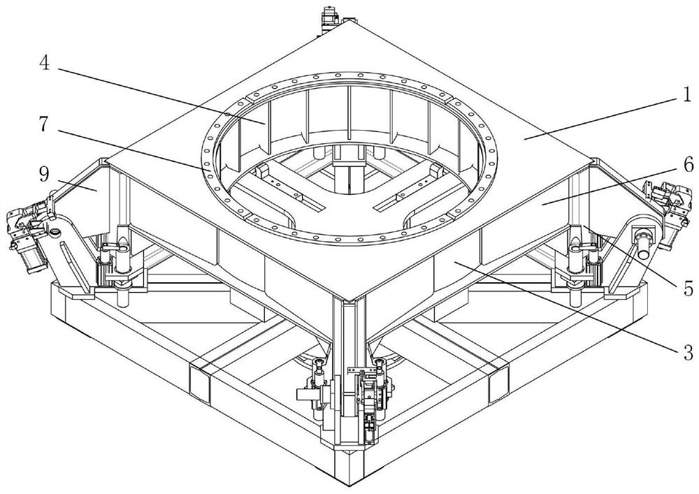
[0050] In this embodiment, the support is the lower support of the tower crane turntable, such as image 3 and Figure 4 As shown, the welding steps of the lower support are roughly the same as those in Embodiment 1, the difference is that the lower support also includes jacking ears 9, and the welding method of the support also includes step S8 performed after step S7: placing the jacking ears 9 Position and clamp on the outrigger assembly 5, and weld the to-be-welded part between the outrigger assembly 5 and the jacking ear 9. In this way, the jacking ears 9 are prevented from interfering with the clamping of the outrigger assembly 5, and the interference of the jacking ears 9 with the welding torch of the welding robot can also be avoided.


PUM


Abstract

The invention discloses a tower crane turntable support welding method. A support comprises an upper cover plate, a lower cover plate, a circular sealing plate, a rib plate, a supporting leg assembly,a surrounding plate and a seat ring. The tower crane turntable support welding method comprises the steps that spot welding is sequentially carried out on the to-be-welded positions between the supporting leg assembly and the lower cover plate, between the lower cover plate and the circular sealing plate, between the circular sealing plate and the rib plate, between the lower cover plate and thesurrounding plate, between the circular sealing plate and the upper cover plate, between the surrounding plate and the upper cover plate and between the upper cover plate and the seat ring from bottomto top, and the to-be-welded positions after spot welding are welded. The tower crane turntable support welding method has the advantages of being simple in step, rapid and easy to implement, high inwelding efficiency, high in automation degree, high in safety performance and the like.

Description

technical field [0001] The invention relates to the technical field of welding technology, in particular to a welding method for a turret support of a tower crane. Background technique [0002] The support of the tower crane turret includes upper and lower cover plates, circular sealing plates, rib plates, outrigger components, coaming plates and peripheral plates and other components. The welding method of the existing tower crane turret support usually adopts the following process flow: [0003] One: Use the marking method to assemble the upper and lower cover plates, circular sealing plates and ribs to form an overall frame structure; [0004] Two: Weld the assembled overall frame structure; [0005] Three: Move the welded overall frame structural parts to the positioning position of the outrigger components, and use special tooling to assemble the outrigger components, hoardings, peripheral plates and overall frame structural parts to form tower crane turret supports; ...

Claims


Application Information

Patent Timeline
IPC IPC(8): B23K31/02B23K37/04B23K37/00
CPCB23K31/02B23K37/0443B23K37/00
Inventor 黄立新梁乾涂辉肖思远莫金竹
Owner HUNAN JOINFRONT WELDING TECH
Features
  • R&D
  • Intellectual Property
  • Life Sciences
  • Materials
  • Tech Scout
  • Unparalleled Data Quality
  • Higher Quality Content
  • 60% Fewer Hallucinations
Learn More