Building cement uniform stirring device

A technology for uniform mixing and construction, applied in cement mixing devices, clay preparation devices, filtration and separation, etc., can solve problems such as slow mixing speed, and achieve the effect of increasing applicability, increasing practicability, and speeding up mixing speed.

Inactive Publication Date: 2020-12-01
杨聪
View PDF0 Cites 2 Cited by
  • Summary
  • Abstract
  • Description
  • Claims
  • Application Information

AI Technical Summary

Problems solved by technology

[0004] The existing cement mixing device for construction has the same stirring direction, and the rotational force in the same direction is always applied to the cement, and the stirring speed is slow. Therefore, a uniform cement mixing device for construction that causes multiple rotations to the cement is needed

Method used


Image

  • Building cement uniform stirring device
  • Building cement uniform stirring device
  • Building cement uniform stirring device

Examples


Embodiment 1

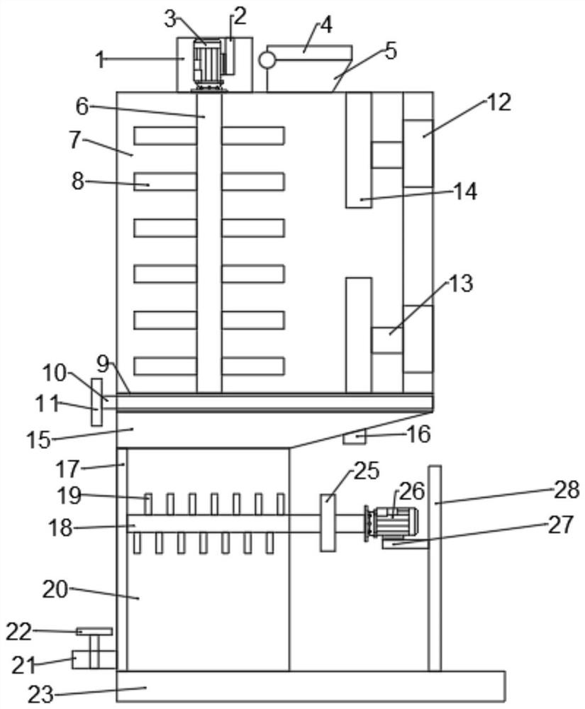
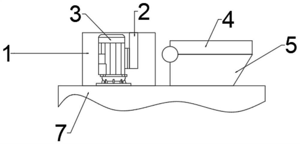
[0033] refer to Figure 1 to Figure 4 , a cement uniform mixing device for construction, comprising a mixing box 7, a power box 1 is connected with a bolt above the mixing box 7, a first fixing plate 2 is connected with a bolt at the top of the inside of the power box 1, and the left side of the first fixing plate 2 The first motor 3 is connected by bolts, the output end shaft of the first motor 3 is connected with the stirring shaft 6, the stirring shaft 6 runs through the upper shell wall of the stirring box 7, the stirring rod 8 is connected with the bolts on the stirring shaft 6, the stirring box 7 The upper right bolt is connected with the feed port 5, the feed port 5 is internally connected with the mixing box 7, and the inner right side of the mixing box 7 is connected with several hydraulic pipes 12, and the left end of the hydraulic pipe 12 is plugged and connected with a hydraulic telescopic pipe 13. The end of the hydraulic telescopic tube 13 away from the hydraulic...

Embodiment 2

[0041] refer to Figure 5 , a cement uniform mixing device for construction. Compared with Embodiment 1, this embodiment has a driving gear 25 fixed on one end of the sliding stirring shaft 18 close to the second motor 26, and a driven gear 29 meshingly connected to the bottom of the driving gear 25. , the central axis of the driven gear 29 is fixed with a transmission shaft 30, and one end shaft of the transmission shaft 30 away from the driven gear 29 is fixed with a sliding gear 31, and the rear side of the sliding gear 31 is meshed with a rack 24, the rack 24 and the base plate 23 Bolt connection, use the sliding stirring shaft 18 to rotate, so that the driving gear 25 drives the driven gear 29 to rotate, so that the transmission shaft 30 drives the sliding gear 31 to rotate, so that the sliding gear 31 moves up and down on the rack 24, thereby completing the concrete mixing. Fully stir and mix well to increase its practicability.

[0042] Working principle: use the slidi...


PUM


Abstract

The invention discloses a cement uniform stirring device for a building. The device includes a stirring box, a power box is arranged above the stirring box; a first fixing plate is arranged at the upper part in the power box; a first motor is arranged on the left side of the first fixing plate, a stirring shaft is arranged at the output end of the first motor and penetrates through the upper sideshell wall of the stirring box, a stirring rod is arranged on the stirring shaft, a feeding port is formed in the right side of the upper portion of the stirring box and communicates with the interiorof the stirring box, and a hydraulic telescopic pipe is arranged at the left end of the hydraulic pipe. Cement is fed through the feeding port; a first motor is started, the stirring shaft drives thestirring rod to rotate; the cement does circumferential movement, and the stirring effect becomes better, and after stirring is completed, the cement enters the funnel through the filter plate, enters the uniform stirring box from the funnel and is stirred under the action of the uniform stirring box, the cement is fully stirred and uniformly stirred in multiple stirring modes, the stirring timeis greatly shortened, and the cement stirring device is suitable for large-scale popularization.

Description

technical field [0001] The invention relates to the technical field of construction, in particular to a cement uniform mixing device for construction. Background technique [0002] Architecture, ancient buildings are mainly wooden structures, while traditional western buildings are mainly masonry structures. Modern buildings are dominated by reinforced concrete. [0003] Cement, powdery hydraulic inorganic gelling material. After adding water and stirring, it becomes a slurry, which can be hardened in the air or better hardened in water, and can firmly bind sand, stone and other materials together. In the early years the mixture of lime and volcanic ash is very similar to lime pozzolanic cement, use it to glue concrete which made of crushed stone. After hardening, the cement not only has high strength, but also can resist the erosion of fresh water or salt water. For a long time, as an important cementing material, it is widely used in civil engineering, water conservancy...

Claims


Application Information

Patent Timeline
Patent Type & Authority Applications(China)
IPC IPC(8): B28C5/16B28C5/14B28C5/08B01D29/03
CPCB01D29/03B28C5/0806B28C5/0818B28C5/0831B28C5/148B28C5/16
Inventor 杨聪
Owner 杨聪
Why Eureka
Try Eureka