Inner core of ultrasonic oil-removing range hood
A range hood, ultrasonic technology, applied in the direction of oil fume removal, household stoves/stoves, heating methods, etc., can solve the problems of consuming manpower, material and financial resources, affecting the exhaust efficiency of oil fume, and being easy to be contaminated with oil, so as to reduce consumption and facilitate Effects of replacement and maintenance and protection of the air environment
- Summary
- Abstract
- Description
- Claims
- Application Information
AI Technical Summary
Problems solved by technology
Method used
Image
Examples
specific Embodiment 1
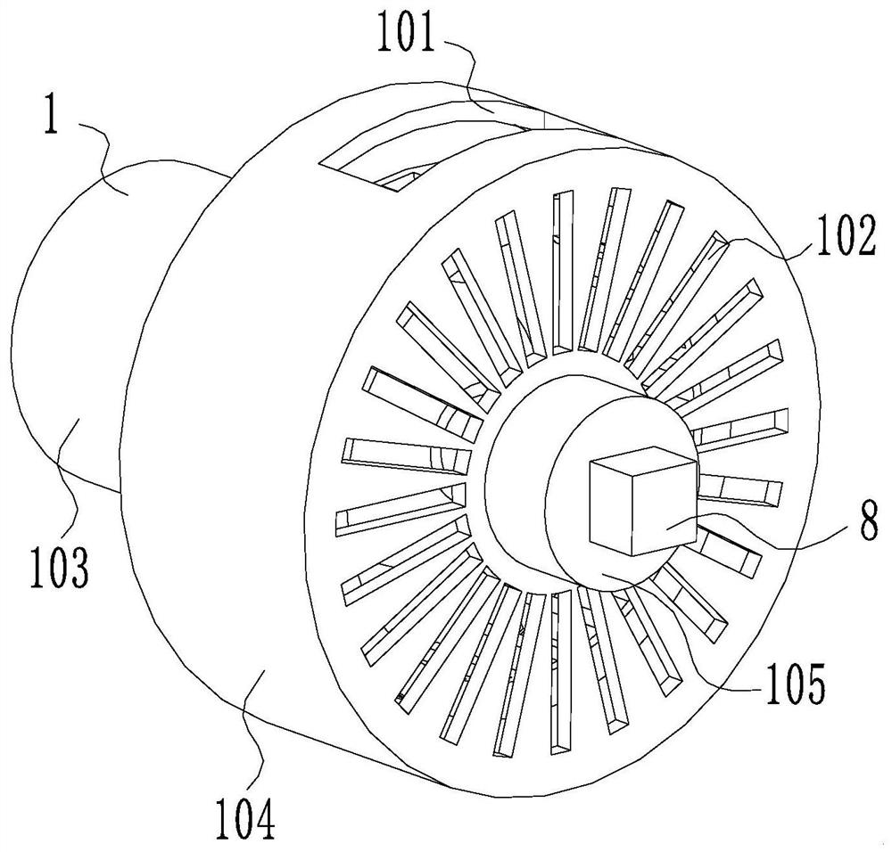
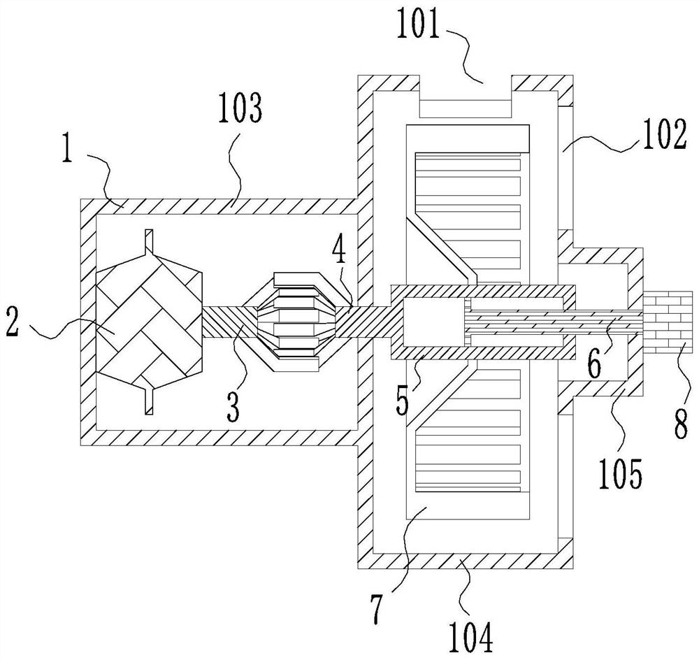
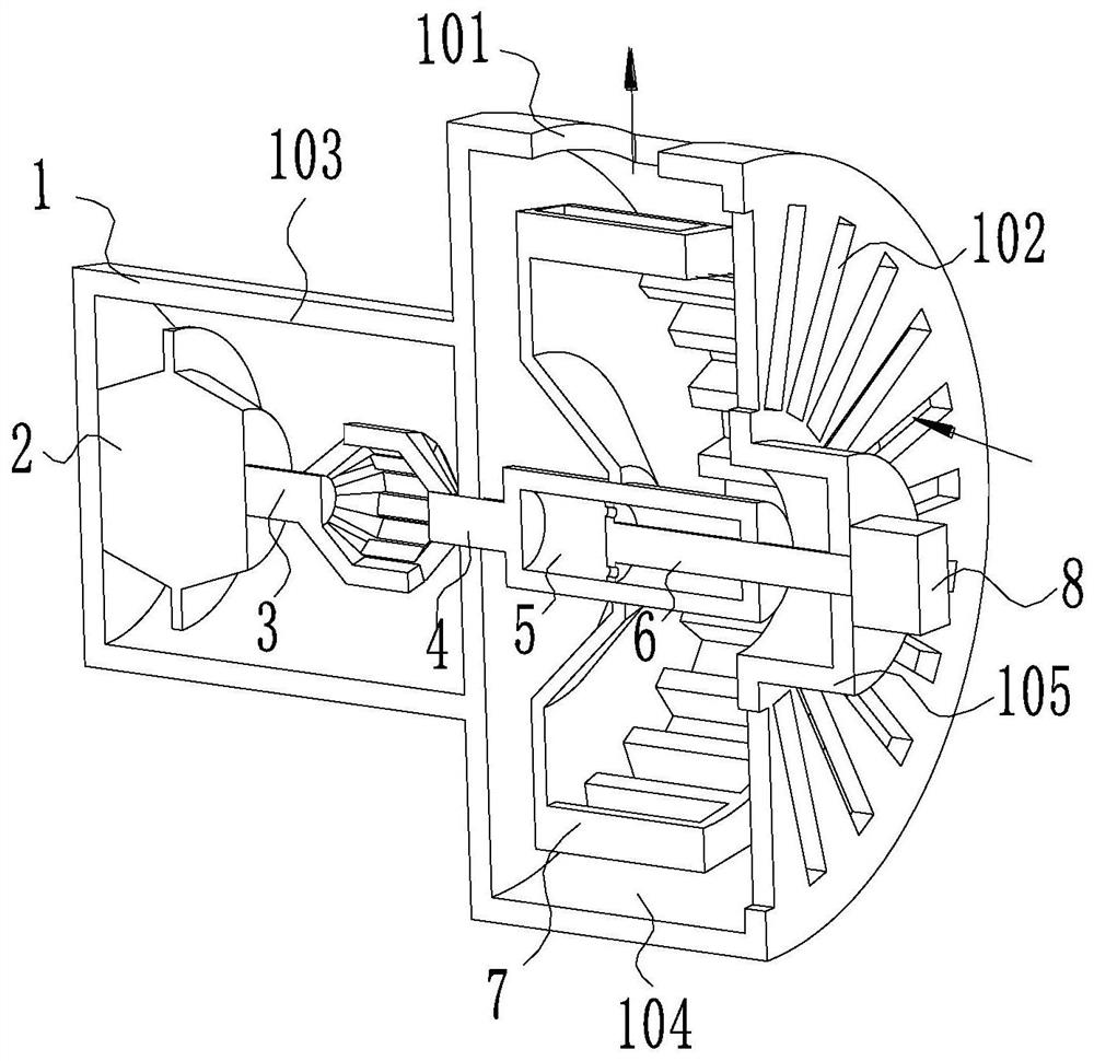
[0049] Specific embodiment one: please refer to Figure 1-7 An inner core of an ultrasonic degreasing range hood, which includes a housing 1, a rotating motor 2, an output claw head rod 3, an input claw head rod 4, a piston housing 5, a piston rod 6, an impeller 7 and an ultrasonic generator 8 .
[0050] The axes of the casing 1, the rotating motor 2, the output claw head rod 3, the input claw head rod 4, the piston housing 5, the piston rod 6, the impeller 7 and the ultrasonic generator 8 are all located on the same straight line.
[0051] The casing 1 includes a motor cavity 103 , an impeller cavity 104 and a vibration cavity 105 distributed in sequence from left to right.
[0052] The right end of the motor chamber 103 is screwed to the left end of the impeller chamber 104, and the right end of the impeller chamber 104 is connected to the left end of the vibrating chamber 105 by screws, so as to facilitate disassembly and installation of the housing and facilitate the repl...
specific Embodiment 2
[0073] Specific embodiment two: elastic pads are fixedly connected between the ultrasonic generator 8 and the vibration cavity 105, and the elastic pads prevent the vibration of the ultrasonic generator 8 from being transmitted to the housing 1, effectively preventing the housing 1 from vibrating for a long time And damage will affect the service life.
specific Embodiment 3
[0074] Specific embodiment three: a spring is fixedly connected between the claw teeth 302 of each output claw head bar 3 and the claw teeth 302 of the adjacent input claw head rod 4, and when the machine is shut down, the spring is in a natural state. When working, the high-frequency vibration passes through the vibrating rod 601, the piston 602, the piston housing 5, the impeller 7 in turn until the input claw head rod 4, because the claw teeth 302 of the output claw head rod 3 and the claws of the adjacent input claw head rod 4 A spring is arranged between the teeth 302, and the spring can resolve the influence of high-frequency vibration on the output claw head rod 3, thereby ensuring the service life of the rotating motor 2.
[0075] Working principle: When the application is in the normal state of oil fume extraction, the rotating motor 2 works to drive the output claw head rod 3 to rotate, the claw teeth 302 of the output claw head rod 3 contact with the claw teeth 302 o...
PUM
 Abstract
Description
Claims
Application Information
 - R&D
- Intellectual Property
- Life Sciences
- Materials
- Tech Scout
- Unparalleled Data Quality
- Higher Quality Content
- 60% Fewer Hallucinations
Browse by: Latest US Patents, China's latest patents, Technical Efficacy Thesaurus, Application Domain, Technology Topic, Popular Technical Reports.
© 2025 PatSnap. All rights reserved.Legal|Privacy policy|Modern Slavery Act Transparency Statement|Sitemap|About US| Contact US: help@patsnap.com


