[0034] The embodiments of the present invention will be described in detail with reference to the accompanying drawings, but the present invention can be implemented in many different ways defined and covered by the claims.
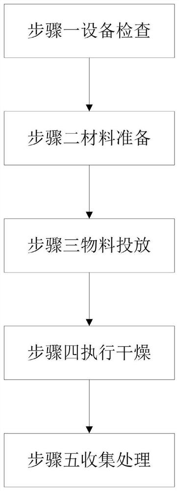
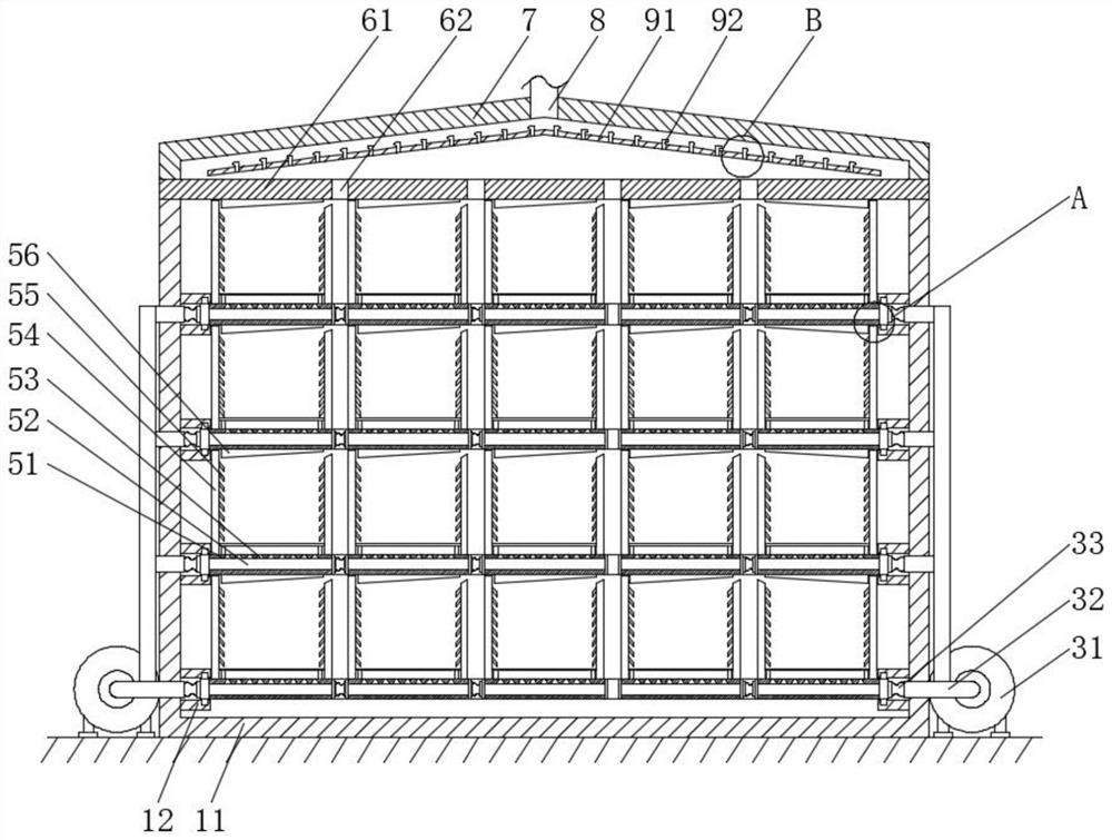
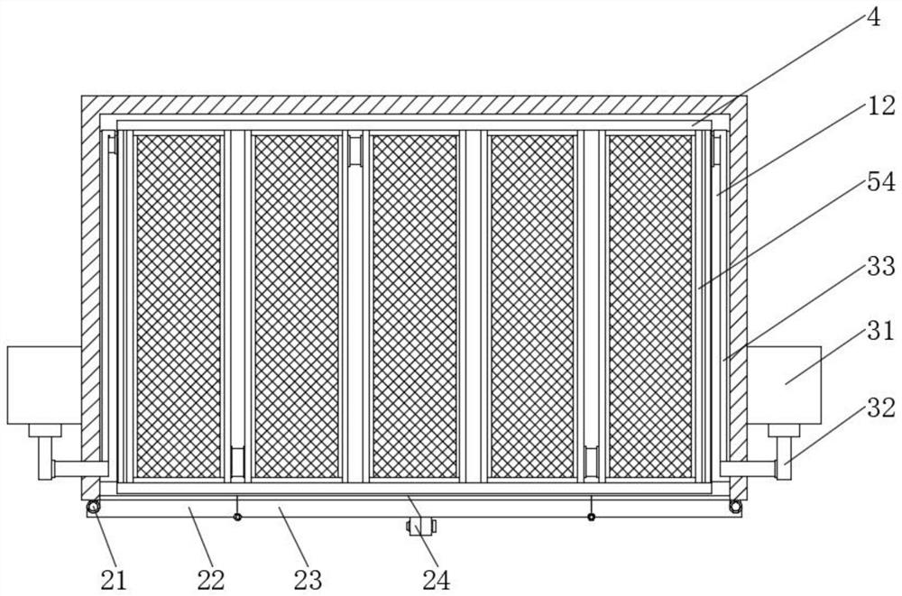
[0035] such as 1 to 7 As shown, a preparation method of filter adsorption material uses a drying treatment equipment, which includes a box body 1, the front of which is movably provided with a sealing door 2, the left and right sides of the box body 1 are respectively fixedly provided with an air supply device 3, the back inside the box body 1 is fixedly provided with an installation plate 4, one end of the air supply device 3 is fixedly connected with a drying isolation bin 5 inside the box body 1, and the top end of the box body 1 is fixedly provided with a top plate 6. A top cover 7 is fixedly arranged on the upper surface of the top plate 6, an air outlet pipe 8 is fixedly arranged in the middle of the top cover 7, and a triangular buffer device 9 is fixedly arranged between the top plate 6 and the top cover 7;
[0036] The method for preparing the filter adsorption material by using the drying treatment equipment comprises the following steps:
[0037] Step 1, equipment inspection, starting the drying equipment to check its operation, so as to ensure the normal operation of the equipment in the process of preparing the filter adsorption material;
[0038] Step two, material preparation, namely, uniformly collecting the activated carbon to be dried, weighing, and placing separately;
[0039] Step three, putting materials, namely placing the weighed activated carbon into the dry isolation bin 5 of the box body 1 in order, and closing the box body 1;
[0040] Step four, drying, namely, drying the activated carbon of the drying isolation bin 5 by the air supply device 3;
[0041] Step five, collecting: taking out the dried activated carbon from the box body 1 and collecting uniformly;
[0042] The box body 1 comprises an outer wall 11 which is fixedly arranged on the ground, and two sides of the inner wall of the outer wall 11 are fixedly provided with limited sliding plates 12 at equal intervals, and the inner part of the limited sliding plates 12 is in a groove shape, and slideways are respectively arranged on the upper and lower surfaces;
[0043] The sealed door 2 includes mounting shafts 21 fixedly mounted on the front faces of the left and right sides of the outer wall 11, two mounting shafts 21 movably mounted with first sealed doors 22, one end of the first sealed door 22 movably mounted with a rotatable second sealed door 23, and one end of the two second sealed doors 23 in contact with each other fixedly mounted with a lock ring 24.
[0044] The air supply device 3 comprises a hot air machine 31 fixedly installed on the ground, the front of the hot air machine 31 is fixedly provided with a conveying pipe 32, and one end of the conveying pipe 32 is fixedly provided with a connecting pipe 33;
[0045]The drying compartment 5 comprises a bottom plate 51 movably installed on the slide way inside the limiting slide plate 12, with an empty slot 52 in the bottom plate 51, air outlets 53 on the upper surface of the bottom plate 51 at equal intervals, side plates 54 fixedly installed on the left and right sides of the upper surface of the bottom plate 51, baffle plates 55 fixedly installed on the opposite surfaces of the two side plates 54 at equal intervals, and flow guide plates 56 fixedly installed on the lower surface of the bottom plate 51.
[0046] The top plate 6 includes a baffle 61 fixedly installed on the top of the outer wall 11, and the baffle 61 is provided with vents 62 at equal intervals.
[0047] The triangular buffer device 9 comprises a sharp plate 91 fixedly installed between the top plate 6 and the top cover 7, and the sharp plate 91 is fixedly provided with backflow nozzles 92 at equal intervals.
[0048] Among them, the connecting shaft between the first sealed door 22 and the second sealed door 23 is installed on the front side of the first sealed door 22 and the second sealed door 23, and the sealing contact surface between the two second sealed doors 23 is an inclined plane. By setting the connecting shaft between the first sealed door 22 and the second sealed door 23 on the front side, the second sealed door 23 can be rotated to the front side of the first sealed door 22 around the connecting shaft. In this way, the door with the original width half of the front width of the outer wall 11 can be folded into a shorter folding door, and then rotated around the installation shaft 21 to open it, which can well reduce the space required for opening the door and the space occupied by the equipment. At the same time, the sealing end of the inclined plane can ensure that the end faces of the second sealed doors 23 on both sides can be completely attached together when closed, thus achieving a good thermal insulation effect.
[0049] The left and right sides of the bottom plate 51 are respectively provided with through holes, the through hole at one end of the bottom plate 51 is fixedly connected with the connecting pipe 33, and the through holes between two adjacent bottom plates 51 are connected by hoses, and the end of the conveying pipe 32 is opposite to the end where the through hole of the connected bottom plate 51 is located, and the dry hot air generated by the hot air machine 31 is conveyed into the empty slot 52 inside the bottom plate 51 through the connecting pipe 33. In this way, it can be ensured that the bulk activated carbon in each drying isolation bin 5 can have separate drying hot air, so as to ensure the drying quality. At the same time, the push-pull action of the drying isolation bin 5 can be realized through the connection of the connecting pipe 33, so as to ensure that one group of activated carbon can be pulled out of the drying isolation bin 5 smoothly after drying, and the next group of activated carbon to be dried can be replaced without losing the conveying capacity of hot air, thus ensuring the drying quality requirements of the above-mentioned activated carbon.
[0050] Among them, the through holes on both sides of the bottom plate 51 are respectively provided with one end on the front and back of the bottom plate 51, and the bottom plate 51 on the edge is connected with the connecting pipe 33 so that the dry hot air can enter the empty slot 52. The through holes on the front and back can well ensure that the air outlet end of the empty slot 52 can discharge the excess dry hot air on the premise that the empty slot 52 can be completely filled with dry hot air. In this way, it can perfectly ensure that enough hot air is discharged from each air outlet 53 to dry the activated carbon, so as to achieve the high-quality drying effect of the activated carbon in each drying isolation bin 5, and thus improve the quality of the activated carbon.
[0051] Among them, the upper surface of the bottom plate 51 is located between two side plates 54 and a grid plate is fixedly installed, and there is a certain height difference between the grid plate and the air outlet 53 opened at the upper part of the bottom plate 51. The opening shape of the air outlet 53 is splayed. When the activated carbon is put into the grid plate for drying, the drying hot air ejected from the splayed air outlet 53 will be restricted by its shape in the flow process, and there will be an acceleration process during ejection, so as to increase the speed of the ejected hot air. To ensure the air flow inside and the drying effect on the activated carbon, and the ejected hot air will gather in a large amount in the space left between the grid plate and the upper surface of the bottom plate 51, so that there is high-pressure hot air inside it, which can further improve the flow speed of the dried hot air flowing in the activated carbon for drying, thus further improving the drying effect. At the same time, the hot air accumulated at the bottom can form a constant temperature layer in the drying isolation bin 5 to ensure the drying temperature, which is more conducive to the drying quality of the activated carbon.
[0052] Among them, the baffle plate 55 is fixed on the side of the side plate 54 with its end inclined downward and equally spaced, and its end will stick to the side of the activated carbon when it is dry. The baffle plate 56 is an inclined plate with different heights at both ends, and there is a certain distance between the two drying silos 5. By sticking the side plate 54 to the side of the activated carbon, the hot air sprayed from the bottom can be filled in the side of the activated carbon under the blocking action of the side plate 54, which not only forms an insulation layer, It can also increase the retention time of hot air in it, so as to achieve better drying effect, and the dried hot air flows to the outside of the drying isolation bin 5 under the flow guidance of the flow guide plate 56, so that the dried air with moisture in each drying isolation bin 5 can rise to the top in a concentrated way, and there will be no repeated serial flow of internal air, which ensures that the drying air of each activated carbon is free of moisture and will not be affected by the drying air on other activated carbons, thus greatly improving the drying quality of activated carbon.
[0053] Among them, the sharp plate 91 and the top cover 7 have the same shape and are both sharp, and the backflow nozzles 92 are fixed at the sharp ends of the sharp plate 91 at equal intervals, respectively. The outlets of the backflow nozzles 92 face to both sides, and the ends of the outlets have smaller diameters. The hot air dried below will flow to the top through the gap between the adjacent drying isolation bins 5, and then the hot air will be blocked by the triangular buffer device 9. Under the sharp plate 91, there is an air flow with more in and less out. By using the climbing effect of hot air, the hot air will climb along the lower surface of the sharp plate 91 to the middle, until the excess air on the lower surface of the sharp plate 91 overflows from both sides of the sharp plate 91 and climbs on the upper surface of the sharp plate 91, and the hot air at the lower part will be accelerated and sprayed out to both sides through the action of the counter-current nozzle 92. That is, the flow direction of the climbing airflow on the upper surface of the pointed plate 91 is opposite to that of the ejected airflow, so that the resistance of the climbing airflow is increased, and the thermal insulation effect formed by the triangular buffer device 9 is achieved. At the same time, the water condensed by the hot air containing moisture flowing out of the air outlet pipe 8 will also flow down the upper surface of the pointed plate 91, which will not affect the lower activated carbon drying area, thus ensuring the drying environment of the activated carbon drying area and improving the drying quality of activated carbon.
[0054] When working, open the second sealed door 23, rotate the second sealed door 23 around the connecting shaft at one end to the front of the first sealed door 22, and rotate the second sealed door 23 and the first sealed door 22 as a whole. After opening the door, pull out the drying isolation bin 5 layer by layer, put the block activated carbon to be dried on the grid plate inside the drying isolation bin 5, and close the first sealed door 22 and the second sealed door 23 after all are placed. Screws are screwed into the locking rings 24 at both ends to start the hot air machine 31. The hot dry air generated by the hot air machine 31 is transmitted into the connecting pipe 33 through the conveying pipe 32, and the hot air in the connecting pipe 33 is input into the empty slot 52. Then, the hot air will be sprayed to the bottom of the grid plate from the air outlet 53, and the hot air will be input into other adjacent drying silos 5 through the hoses between them to dry the activated carbon. The dried hot air will enter the interval between adjacent drying silos 5 under the guidance of the guide plate 56, rise to the top of the pointed plate 91, and the hot air will be sprayed out to both sides through the counter-current nozzle 92, forming an insulation layer at the top of the box body 1 to ensure the overall drying effect, and finally the hot air will be discharged through the air outlet pipe 8, completing the whole drying process.
[0055] It is obvious to those skilled in the art that the present invention is not limited to the details of the above exemplary embodiments, but can be implemented in other specific forms without departing from the spirit or essential characteristics of the present invention. Therefore, the embodiments should be regarded as illustrative and non-restrictive in all respects. The scope of the invention is defined by the appended claims rather than the above description, and therefore all changes that fall within the meaning and range of equivalents of the claims are intended to be embraced by the invention. Any reference signs in the claims should not be regarded as limiting the claims involved.
[0056] In addition, it should be understood that although this specification is described in terms of embodiments, not every embodiment only contains an independent technical solution. This description of the specification is only for the sake of clarity. Those skilled in the art should take the specification as a whole, and the technical solutions in each embodiment can also be appropriately combined to form other embodiments that can be understood by those skilled in the art.