Vacuum pressing machine

A technology of vacuum laminating machine and vacuum pad, which is applied in the manufacture of multilayer circuits, electrical components, printed circuits, etc., which can solve the problems of poor bonding force, unqualified appearance, and unfavorable production, so as to prevent delamination and improve Effect of appearance quality and improvement of lamination efficiency

Active Publication Date: 2020-12-01
TOP RANGE MACHINERY
View PDF5 Cites 4 Cited by
  • Summary
  • Abstract
  • Description
  • Claims
  • Application Information

AI Technical Summary

Problems solved by technology

However, to establish a closed vacuum environment around the pressing machine, it is necessary to wait for the time of vacuuming and consume a lot of power, which is not conducive to mass and rapid production; at present, there is another vacuum device that uses the upper and lower heat press plates Vacuum is drawn in between, so that the vacuum state only exists in the plate pressing space, and the action time is from the beginning to the end of pressing. Although the production efficiency can be improved, the edge of the plate is squeezed by the upper and lower hot pressing plates and air suction at the same time. impact, resulting in unqualified appearance and poor bonding force

Method used


Image

  • Vacuum pressing machine
  • Vacuum pressing machine
  • Vacuum pressing machine

Examples


Embodiment Construction

[0049] In order to make the above-mentioned and other purposes, features and advantages of the present invention more obvious and understandable, the following is based on preferred embodiments of the present invention, and is described in detail as follows in conjunction with the accompanying drawings:

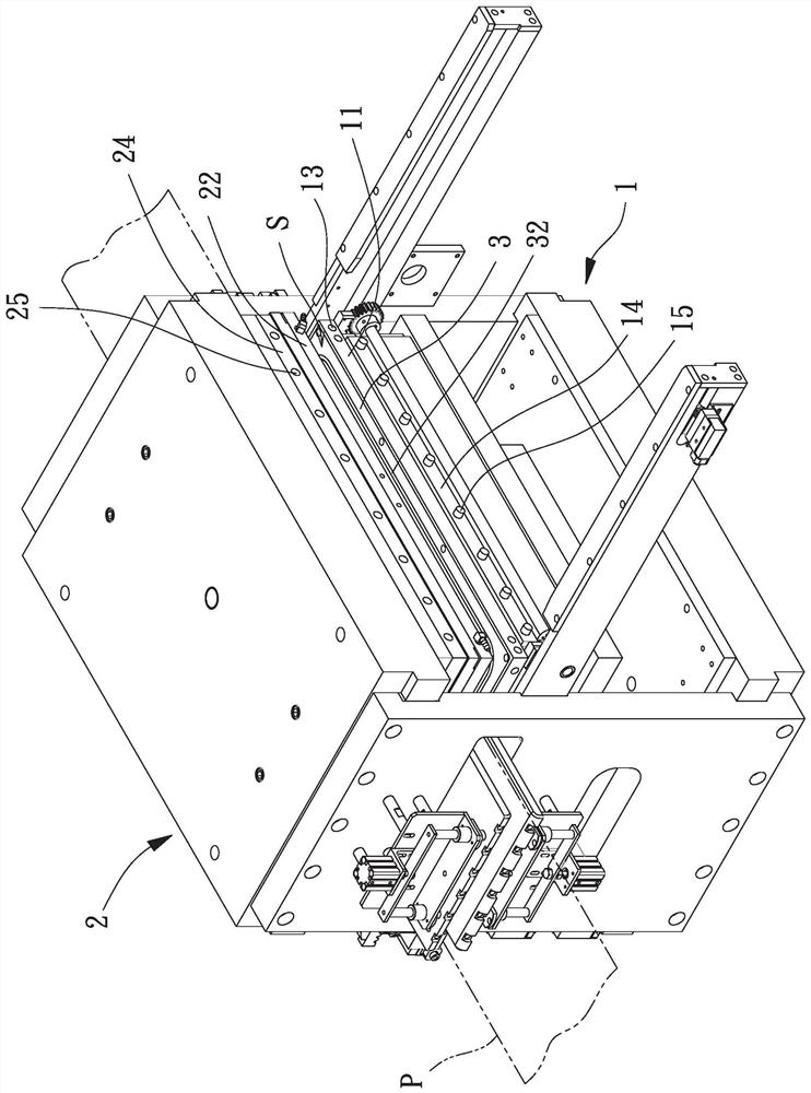
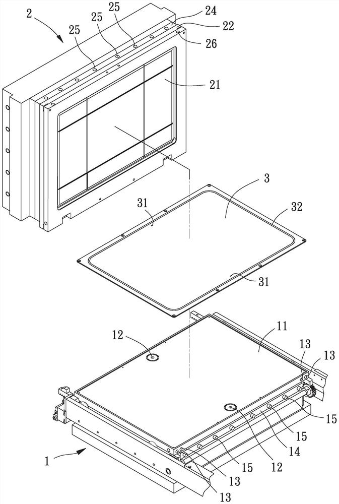
[0050] Please refer to figure 1 and 2 As shown, it is the first embodiment of the vacuum pressing machine of the present invention, including a loading platform 1, a pressing platform 2 and a vacuum pad 3, the pressing platform 2 is parallel and located on the loading platform 1, There is a gap between the loading platform 1 and the pressing platform 2 for a board P to pass through, the vacuum pad 3 is attached to the loading platform 1, and the upper surface of the vacuum pad 3 faces the board P and the pressing board. Combined platform 2.

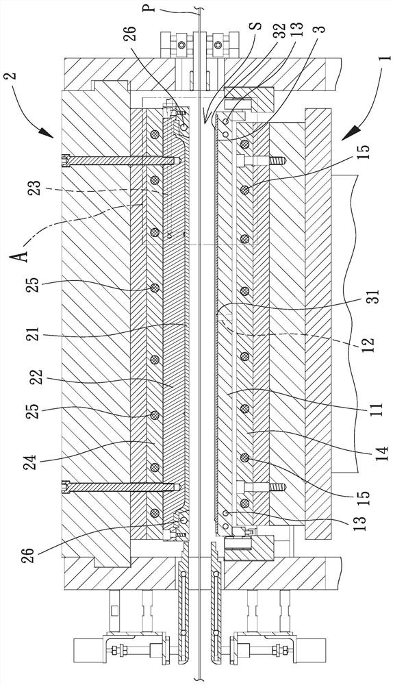
[0051] Please refer to figure 2 and 3 As shown, the loading platform 1 can be reciprocated and vertically lifted. When the loading...


PUM


Abstract

A vacuum pressing machine used for solving a problem that existing vacuum pressing machines cause defects formed on edges of plates is disclosed. The vacuum pressing machine includes an object carrying platform having an air extraction layer and a plurality of apertures arranged in the air extraction layer; a pressing platform having an aerating layer and a pressing pad arranged on a face of the aerating layer and parallel to the air extraction layer; and a vacuum pad arranged on a surface of the air extraction layer facing the pressing pad. The vacuum pad includes a stopper and a plurality ofholes corresponding to and intercommunicating with the plurality of apertures of the air extraction layer. The stopper wall protrudes from another surface of the vacuum pad opposite to the air extraction layer, and surrounds an outer periphery of the vacuum pad. Both the platform and the pressing platform include a plurality of cooling units arranged corresponding to the stopper wall.

Description

technical field [0001] The invention relates to a mechanical device for laminating and pressing plates, in particular to a vacuum pressing machine for improving the quality and appearance of composite plates. Background technique [0002] Printed circuit boards are used to carry various electronic components, and with the application of electronic components tending towards miniaturization and high-density assembly, coupled with a large number of complex connection lines derived from densification, the mounting area on the circuit board is no longer sufficient. Therefore, a multi-layer structure substrate has been developed, which is formed by stacking and pressing multi-layer boards. [0003] Existing vacuum presses can generate high temperature and high pressure to laminate and align the multi-layer sheets, so that the adhesive between the layers can be fused at high temperature, and then the high pressure can strengthen the connection and drive away the residual gas in th...

Claims


Application Information

Patent Timeline
Patent Type & Authority Applications(China)
IPC IPC(8): H05K3/46
CPCH05K3/4611H05K2203/068
Inventor 周进德
Owner TOP RANGE MACHINERY
Why Eureka
Try Eureka