Soup spoon groove stamping device

A technology of punching device and spoon, applied in the field of punching device, can solve the problems of low safety, manual feeding of spoons, manual feeding, etc., and achieve the effects of increasing safety, reducing wear and ensuring aesthetics

Active Publication Date: 2020-12-04
嘉兴市名人电器股份有限公司
View PDF5 Cites 5 Cited by
  • Summary
  • Abstract
  • Description
  • Claims
  • Application Information

AI Technical Summary

Problems solved by technology

[0004] In order to overcome the disadvantages of manual loading and unloading and low safety during the production of spoons, the technical problem is to provide a spoon groove stamping device with high safety, automatic mold push, and automatic discharge

Method used


Image

  • Soup spoon groove stamping device
  • Soup spoon groove stamping device
  • Soup spoon groove stamping device

Examples


Embodiment 1

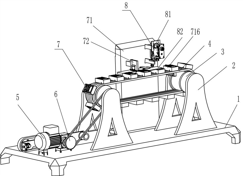
[0065] A spoon groove punching device such as figure 1 and Image 6 As shown, it includes a base 1, a support frame 2, a transmission cylinder 3, a conveyor belt 4, a motor 5, a transmission assembly 6, a blanking mechanism 7, a punching mechanism 8 and a pushing mechanism 9. The top of the base 1 is provided with Support frame 2, a transmission cylinder 3 is rotatably provided between the left support frame 2 and the right support frame 2, a conveyor belt 4 is provided between the outer sides of the transmission cylinder 3, and a motor 5 is provided on the left side of the top of the base 1 , a transmission assembly 6 is arranged between the output shaft of the motor 5 and the transmission cylinder 3 on the left side, a blanking mechanism 7 is arranged between the middle of the rear side of the top of the base 1 and the conveyor belt 4, and a punching mechanism 8 is arranged on the front side of the blanking mechanism 7, The punching mechanism 8 is above the conveyor belt 4 ...

Embodiment 2

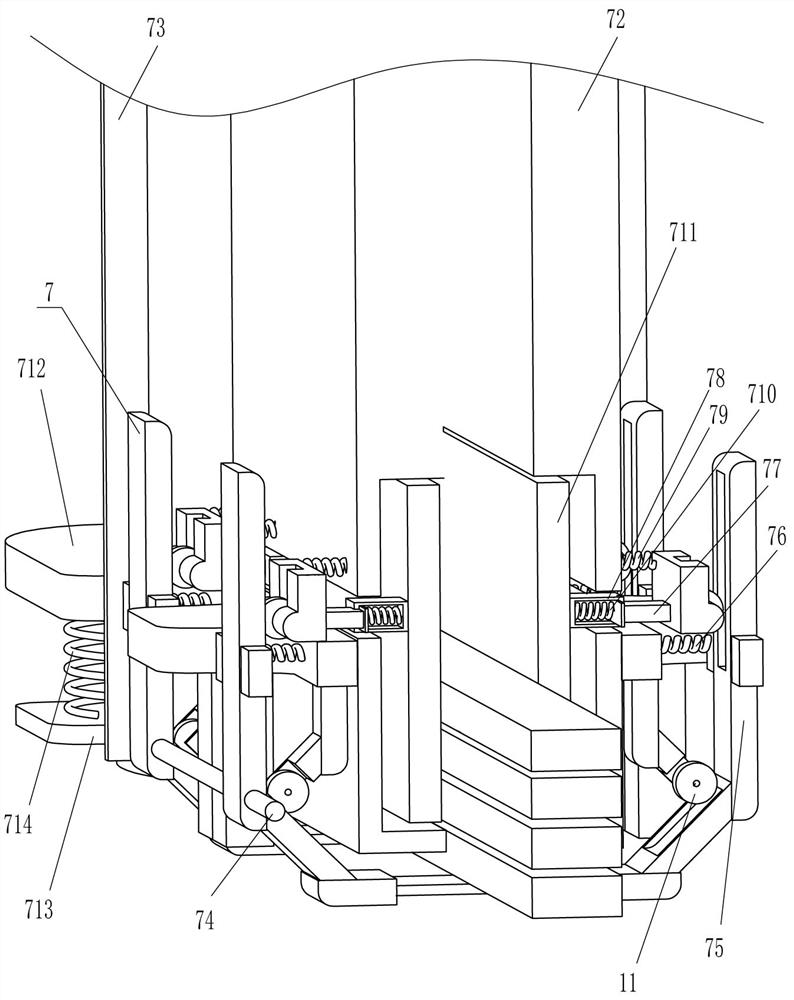
[0068] On the basis of Example 1, as figure 2 , image 3 , Figure 4 , Figure 5 and Image 6 As shown, the unloading mechanism 7 includes a rear side plate 71, a charging frame 72, a bracket 73, a rotating rod 74, an L-shaped blocking piece 75, a first spring 76, a push plate 77, a push block 78, and a second spring 79. Third spring 710, rubber splint 711, sliding plate 712, fixing plate 713, fourth spring 714, first magnet 715, material transport frame 716, sliding block 717, fifth spring 718 and second magnet 719, base 1 The rear side of the top is provided with a rear side plate 71, the front left of the rear side plate 71 is provided with a loading frame 72, the left and right sides of the loading frame 72 are symmetrically provided with fixed plates 713, and the top of the fixed plate 713 is provided with The fourth spring 714, a sliding plate 712 is arranged between the other end of the fourth spring 714, the inner side of the sliding plate 712 is slidably connecte...

Embodiment 3

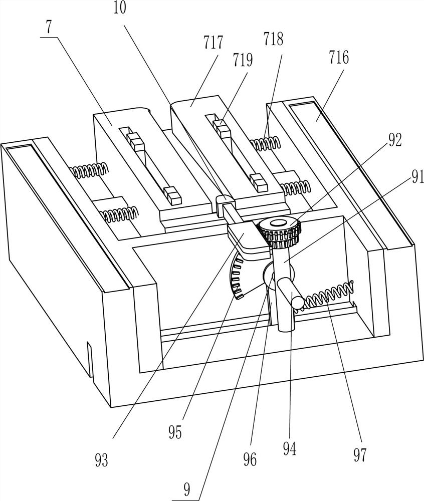
[0073] On the basis of Example 2, as Figure 5 and Image 6 As shown, the pushing mechanism 9 includes a first fixed rod 91, a double gear 92, a rack 93, a second fixed rod 94, a sector gear 95, a contact piece 96, a seventh spring 97 and a contact plate 98. The inner front part of the 716 is provided with a first fixing rod 91; There is a contact piece 96, the bottom of the contact piece 96 passes through the bottom of the material transport frame 716, the lower part of the contact piece 96 is in the slot opened at the bottom of the material transport frame 716, the top of the contact piece 96 is provided with a sector gear 95, the sector gear 95 and the double The lower side of the coupling gear 92 meshes with each other, and a seventh spring 97 is arranged between the lower right side of the contact piece 96 and the right side of the inner wall of the material transport frame 716. The top rear side of the material transport frame 716 is slidably provided with a rack 93. T...


PUM


Abstract

The invention relates to a stamping device, in particular to a soup spoon groove stamping device. The soup spoon groove stamping device is high in safety, and capable of automatically pushing a die and automatically discharging. The soup spoon groove stamping device comprises a base, supporting frames, transmission cylinders, conveyor belts, a motor, a transmission assembly is arranged between theoutput shaft of the motor and the adjacent transmission cylinder; and discharging mechanisms, wherein the supporting frames are arranged on the four sides of the top of the base, the transmission cylinders are rotationally arranged between supporting frames on the same sides, the conveyor belts are arranged on the outer sides of the transmission cylinders, the motor is arranged on one side of thetop of the base, the transmission assembly is arranged between an output shaft of the motor and the adjacent transmission cylinder, and the discharging mechanisms are arranged between the middle of one side of the top of the base and the conveying belts. Through cooperation among the discharging mechanisms, a stamping mechanism and a pushing mechanism, the processes of automatic discharging, stamping and pushing can be achieved, workers do not need to complete these work manually, the workers are prevented from being accidentally injured by a stamping machine, and thus the safety is improved,and the working efficiency is improved.

Description

technical field [0001] The invention relates to a punching device, in particular to a spoon groove punching device. Background technique [0002] A spoon is a very common tool in life. It can be used to drink soup, serve rice, eat, etc. It is also called a spoon for drinking soup. The groove of the spoon will be deeper. Now most of the spoons we use in our lives are made of stainless steel. The advantage of stainless steel tableware is that it is not suitable for breeding bacteria. [0003] When making a spoon, workers need to manually put the steel under the stamping tool to make a mold, and then take it out. After taking it out, a groove needs to be punched out by a punching machine on the head of the prepared spoon mold, which is convenient for the spoon Use, cycle operation, in the stamping process, it will be accidentally pressed to the hands of the workers by the stamping machine, which is not safe for the workers, and the work efficiency is not high. Safety and work...

Claims


Application Information

Patent Timeline
Patent Type & Authority Applications(China)
IPC IPC(8): B21D22/06B21D53/62B21D43/12B21D45/02
CPCB21D22/06B21D53/62B21D43/12B21D45/02
Inventor 曹云峰
Owner 嘉兴市名人电器股份有限公司
Why Eureka
Try Eureka