Composite electric spindle

A technology of electric spindle and headstock, which is applied in the direction of large fixed members, metal processing machinery parts, metal processing equipment, etc., can solve the problems of composite electric spindle restricting the application place of composite electric spindle, achieve simple structure, reduce axial length, The effect of simplifying assembly

Active Publication Date: 2020-12-04
LUOYANG BEARING RES INST CO LTD
View PDF7 Cites 2 Cited by
  • Summary
  • Abstract
  • Description
  • Claims
  • Application Information

AI Technical Summary

Problems solved by technology

[0005] The purpose of the present invention is to provide a composite electric spindle to solve the technical problem in the prior art that the three-gear mechanism for milling and turning conversion is arranged on the front side, resulting in a thicker front end of the composite electric spindle and limiting the application of the composite electric spindle

Method used


Image

  • Composite electric spindle
  • Composite electric spindle
  • Composite electric spindle

Examples


specific Embodiment 1

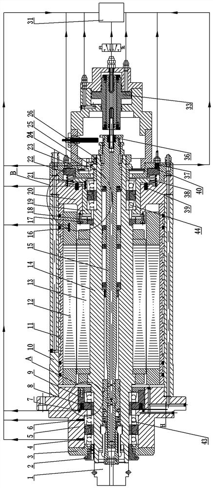
[0040] like Figure 1 to Figure 3 As shown, the composite electric spindle in this embodiment includes a headstock, and a motor and a rotating shaft 14 are arranged inside the headstock, and a front bearing support structure 43 and a rear bearing support structure 44 are arranged corresponding to the rotating shaft 14 to play the role of rotation support. The motor includes a motor stator 12 and a motor rotor 13. The motor stator 12 and the motor rotor 13 are located between the front bearing support structure 43 and the rear bearing support structure 44 to act as a power source. The motor rotor 13 is fixedly assembled with the rotating shaft 14, and the rotating shaft The center of 14 is provided with a broach system 15 and a rotary joint connecting rod 36 to play the role of rapid tool change and central cooling. The front end of the rotary joint pull rod 36 is connected to the broach system 15, and the rear end is connected to the driving piston 33 for releasing the knife. ...

specific Embodiment 2

[0069] The main difference between it and Embodiment 1 is that in Embodiment 1, the front end of the rear bearing seat is integrated with the floating toothed disc. On the basis of the integrated arrangement of the floating toothed disc and the rear bearing seat, in this embodiment, the floating The body is fixedly installed on the front end of the rear bearing seat, and can be fixed and installed by screws.

specific Embodiment 3

[0071] It differs from Embodiment 1 mainly in that: in Embodiment 1, the three toothed disc mechanism is located at the rear side of the motor rotor, and the floating toothed disc is integrated and arranged on the rear bearing seat, and is arranged on the rear side to reduce the front end of the composite electric spindle. For the purpose of radial dimension, in this embodiment, the floating chainring of the three-sprocket mechanism is completely separated from the rear bearing seat, the rear bearing support structure is arranged in front, and the three-sprocket mechanism is located at the rear side of the rear bearing support structure. The movable toothed plate with large radial size is assembled with the rotating shaft. The floating toothed plate can be guided and moved along the front and rear direction and assembled on the rear end cover. The fixed toothed plate is clamped and fixed between the rear inner cover and the rear end cover. By locking the top of the piston Pushi...


PUM


Abstract

The invention relates to a composite electric spindle. The composite electric spindle comprises a spindle box, a motor and a rotating shaft, wherein the rotating shaft is fixedly assembled with a motor rotor; the front end of the rotating shaft is used for installing a machining cutter; the rotating shaft is rotatably supported by a front bearing supporting structure and a rear bearing supportingstructure; a three-toothed-disc mechanism is arranged on the rear side of the motor rotor and comprises a floating toothed disc, a movable toothed disc and a fixed toothed disc; the fixed toothed discis relatively and fixedly assembled on the spindle box; the movable toothed disc is relatively and fixedly assembled on the rotating shaft; the floating toothed disc is movably assembled on the spindle box in the front-rear direction; and the floating toothed disc is provided with a combination position in the moving stroke, and the floating toothed disc meshes with the movable toothed disc and the fixed toothed disc at the same time when the floating toothed disc is in the combination position. According to the composite electric spindle, the three-toothed-disc mechanism is positioned on therear side of the motor rotor, so that compared with the prior art that a three-toothed-disc mechanism is arranged on the front side of a motor rotor, the radial size of the front end of the compositeelectric spindle is effectively reduced, and then the application fields of the composite electric spindle are effectively expanded.

Description

technical field [0001] The invention relates to a composite electric spindle. Background technique [0002] In recent years, composite processing technology and intelligent manufacturing technology have become popular development directions in the field of mechanical processing. Intelligent composite processing technology is an advanced manufacturing technology. Compared with traditional single-function processing technology, intelligent composite processing After the workpiece is installed once, the surface processing of the parts is completed sequentially or multiple times with various manufacturing methods, and the processing process is monitored in real time. The most widely used compound machining and the most difficult is the compound machining of milling and turning conversion. As one of the key components of CNC machine tools, the high-speed electric spindle "combines the motor and the machine tool spindle into one", and the machine tool spindle is directly connected...

Claims


Application Information

Patent Timeline
Patent Type & Authority Applications(China)
IPC IPC(8): B23B19/02B23B19/00
CPCB23Q1/70
Inventor 李东亚黄昆宋思明叶军牛青波郑昊天张振强
Owner LUOYANG BEARING RES INST CO LTD
Why Eureka
Try Eureka