Slender shaft auxiliary machining equipment for numerically controlled lathe

A technology of CNC lathes and auxiliary equipment, which is applied in the direction of metal processing equipment, turning equipment, auxiliary equipment, etc., can solve problems such as processing errors of slender shafts, and achieve the effects of avoiding processing errors, good use effects, and improving precision

Inactive Publication Date: 2020-12-04
杨兰
0 Cites 0 Cited by

AI-Extracted Technical Summary

Problems solved by technology

However, this method requires multiple clamping of the slender shaft, and multip...

Method used

As shown in Figure 4, 5, 6, some spur gears 24 corresponding to the T-shaped guide block 20 one-to-one are installed on the above-mentioned shaft B25; a T-shaped guide block in the adjacent two T-shaped guide blocks 20 The arc-shaped rack A22 concentric with the T-shaped guide block 20 is installed on the convex arc surface of 20 through two fixed blocks A21, and the other T-shaped guide block 20 in the adjacent two T-shaped guide blocks 20 The curved rack B23 is installed on the convex arc surface. The teeth on the concave arc surface of the arc rack A22 mesh with the corresponding spur gear 24, and the teeth on the convex arc surface of the arc rack A22 mesh with the corresponding spur gear 24, ensuring that two adjacent T-shaped The direction of movement of the guide block 20 around the central axis of the arc-shaped support 16 is opposite, so that the two adjacent telescopic rod mechanisms B50 or the adjacent telescopic rod mechanisms A31 and telescopic rod mechanisms B50 form a certain degree of coverage on the elongated shaft 6 The pressure is effectively prevented from vibrating due to the poor strength of the elongated shaft 6 during rotation. As shown in Figures 5 and 9, two fixed blocks A21 pass through the movable slots 18 on the convex arc surface of the corresponding arc brackets 16; as shown in Figure 3, several arc brackets 16 are connected by connecting rods 30 to increase The intensity of large arc support 16; As shown in Figure 8, a U-shaped seat A29 is installed on the arc support 16, and the rotation on the U-shaped seat A29 is equipped with a worm screw 27, and a manual crank is installed on one end of the worm screw 27; Meshes with the worm gear 26 mounted on the shaft B25.
At the same time, two adjacent telescopic rod mechanisms B50 o...

Abstract

The invention belongs to the field of lathe auxiliary machining equipment, and particularly relates to slender shaft auxiliary machining equipment for a numerically controlled lathe. The slender shaftcomprises a base, a sliding seat, a screw rod A, an arc-shaped bracket, a support seat B, a T-shaped guide block, a shaft B, telescopic rod mechanisms A and telescopic rod mechanisms B, wherein the base is arranged on a machine tool body; and the sliding seat is in sliding fit with the interior of a sliding groove A in the base in the direction perpendicular to the slender shaft. In a turning process of the slender shaft, the two telescopic rod mechanisms A and the multiple telescopic rod mechanisms B are used for pressing the slender shaft in a staggered mode at a certain angle to prevent the slender shaft from being bent by a turning tool. Moreover, the slender shaft does not need to be repeatedly clamped for multiple times in an auxiliary slender shaft machining process, machining errors caused by repeated clamping in the slender shaft machining process are avoided, and machining precision and machining efficiency of the slender shaft are effectively improved.

Application Domain

Technology Topic

Image

  • Slender shaft auxiliary machining equipment for numerically controlled lathe
  • Slender shaft auxiliary machining equipment for numerically controlled lathe
  • Slender shaft auxiliary machining equipment for numerically controlled lathe

Examples

  • Experimental program(1)

Example Embodiment

[0036] The accompanying drawings are all schematic diagrams of the implementation of the present invention, so as to understand the principle of structural operation. The specific product structure and proportional size can be determined according to the use environment and conventional technology.
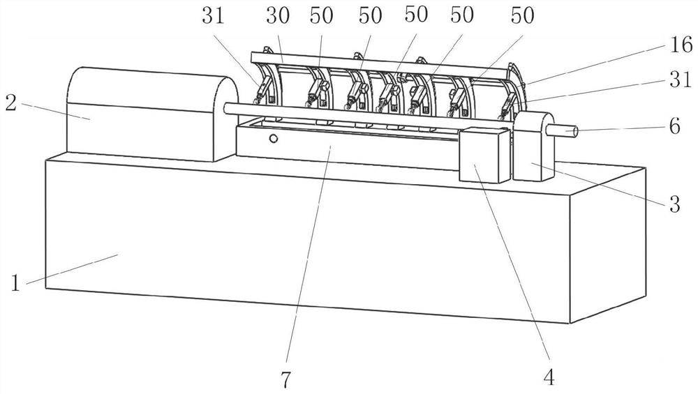
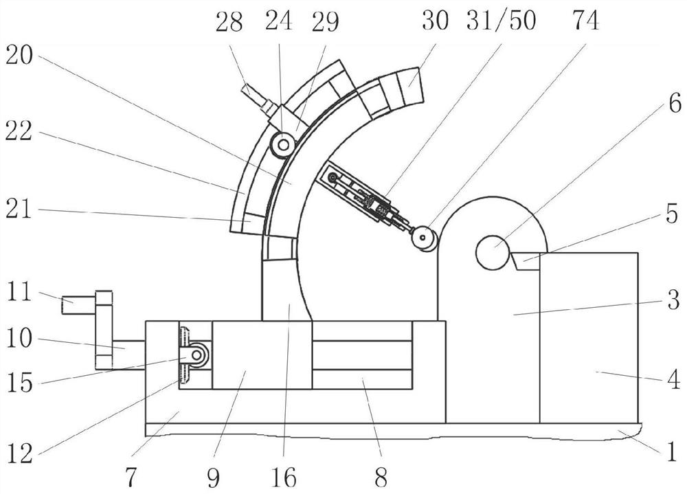
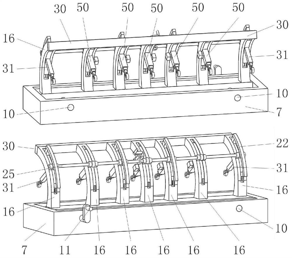
[0037] like image 3 As shown, it includes a base 7, a sliding seat 9, a screw rod A10, an arc bracket 16, a bearing B19, a T-shaped guide block 20, a shaft B25, a telescopic rod mechanism A31, and a telescopic rod mechanism B50. figure 1 , 2 , 7, the base 7 is installed on the bed of the machine tool, and the chute A8 on the base 7 slides in the direction perpendicular to the slender shaft 6 with a sliding seat 9, and the two screw rods A10 that are rotatably matched with the base 7 and the sliding seat 9 Thread fit, constant speed transmission connection between two screw rods A10; figure 1 , 3 As shown, a number of arc-shaped brackets 16 distributed along the axial direction of the slender shaft 6 are installed on the sliding seat 9, and the concave arc surface of the arc-shaped bracket 16 is opposite to the slender shaft 6; Figure 4 , 6 , 9, the arc T-shaped guide block 20 slides in the arc-shaped T-shaped guide groove 17 on each arc-shaped support 16, and the movement directions of two adjacent T-shaped guide blocks 20 are opposite; Figure 5 , 6 , shown in 8, with the axle B25 that the bearing B19 rotation on some arc supports 16 is connected with some T-shaped guide block 20 transmissions, the structure that manual drive shaft B25 is rotated is installed on an arc support 16.
[0038] like image 3 As shown, the concave arc surfaces of the two outermost T-shaped guide blocks 20 are respectively equipped with telescopic rod mechanisms A31 that expand and contract along the radial direction of the arc where the T-shaped guide blocks 20 are located. The concave arc surface of the guide block 20 is equipped with a telescopic rod mechanism B50 that expands and contracts along the radial direction of the arc where the T-shaped guide block 20 is located; figure 1 , 2 As shown, the telescopic rod mechanism A31 and the telescopic rod mechanism B50 cooperate with the slender shaft 6 to prevent the slender shaft 6 from bending under the action of the turning tool 5; Figure 4 , 11 As shown, the telescopic rod mechanism B50 always produces an effective resistance force on the slender shaft 6 whose diameter gradually decreases through the cooperation of its own pressure-sensitive system.
[0039] like figure 1 , 3 As shown, several above-mentioned arc-shaped brackets 16 gradually tend to evacuate from the middle to both sides, so that the relatively weak middle part of the elongated shaft 6 that is far away from the main shaft seat 2 and the tool seat 4 can be replaced by denser pressure rollers B74 Pressing to ensure that the middle part of the slender shaft 6 is not easy to bend during the turning process. like figure 2 As shown, the central axis of the T-shaped guide groove 17 is parallel to the slender shaft 6 and is at the same level as the central axis of the slender shaft 6, ensuring that the telescopic rod mechanism A31 and the telescopic rod mechanism B50 installed on the arc bracket 16 are After approaching the slender shaft 6, an effective pressure can be formed on the slender shaft 6. At the same time, it is ensured that when the arc-shaped support 16 is close to the slender shaft 6, the center axis of the arc-shaped support 16 coincides with the central axis of the slender shaft 6, so that The two adjacent telescopic rod mechanisms B50 that are staggered or the telescopic rod mechanisms B50 and A31 that are staggered can respectively form effective pressure against the elongated shaft 6 in their telescopic directions.
[0040] like figure 2 , 3 , 7, each of the above-mentioned screw rods A10 is equipped with a bevel gear A12, and the two supports A15 installed on the inner wall of the chute A8 are rotated and fitted with an axis A14 parallel to the slender axis 6, and the two ends of the axis A14 are installed symmetrically. The two bevel gears B13 mesh with the two bevel gears A12 respectively; the end of one screw A10 is equipped with a crank handle A11 that manually drives the screw A10 to rotate.
[0041] like Figure 4 , 5 , 6, the above-mentioned shaft B25 is equipped with a number of spur gears 24 corresponding to the T-shaped guide blocks 20 one by one; The two fixed blocks A21 are equipped with an arc-shaped rack A22 that is concentric with the T-shaped guide block 20, and the other T-shaped guide block 20 of the two adjacent T-shaped guide blocks 20 is equipped with an arc-shaped arc surface. shaped rack B23. The teeth on the concave arc surface of the arc rack A22 mesh with the corresponding spur gear 24, and the teeth on the convex arc surface of the arc rack A22 mesh with the corresponding spur gear 24, ensuring that two adjacent T-shaped The direction of movement of the guide block 20 around the central axis of the arc-shaped support 16 is opposite, so that the two adjacent telescopic rod mechanisms B50 or the adjacent telescopic rod mechanisms A31 and telescopic rod mechanisms B50 form a certain degree of coverage on the elongated shaft 6 The pressure is effectively prevented from vibrating due to the poor strength of the elongated shaft 6 during rotation. like Figure 5 , 9 As shown, two fixed blocks A21 pass through the movable groove 18 on the convex arc surface of the corresponding arc bracket 16; image 3 As shown, several arc-shaped supports 16 are fixedly connected by connecting rods 30, to increase the intensity of the arc-shaped supports 16; as Figure 8 As shown, a U-shaped seat A29 is installed on an arc support 16, and the U-shaped seat A29 is rotated with a worm screw 27, and a manual crank is installed at one end of the worm screw 27;
[0042] like Figure 14 As shown, the telescopic rod mechanism A31 includes an outer casing A32, a telescopic sleeve A34, a connecting rod 30B, a slider A38, a bolt 40, a spring A41, a spring B42, an inner rod A43, a slider B44, a spring C46, ​​a spring D47, and a pressing wheel A49. , where as Figure 5 , 14 As shown, in the outer cover A32 installed on the T-shaped guide block 20, a telescopic sleeve A34 is slid radially along the arc bracket 16, and the slider A38 sliding in the outer cover A32 is fixedly connected with the telescopic sleeve A34 through the connecting rod 30B; A spring A41 and a spring B42 to reset it are installed on both sides of the block A38; the threaded hole A39 on the slide block A38 is screwed with a bolt 40 cooperating with the rectangular hole 33 on the overcoat A32; Radial sliding fit with inner rod A43; as Figure 14 , 15 As shown, the slider B44 installed at one end of the inner rod A43 slides in the chute B35 on the inner wall of the telescopic sleeve A34; the spring C46 and the spring D47 for resetting it are installed on both sides of the slider B44; the exposed end of the inner rod A43 is installed U-shaped seat B48 is arranged, and the pressure roller A49 that cooperates with elongated shaft 6 is installed in the U-shaped seat B48.
[0043] like Figure 14 As shown, one end of the above-mentioned spring A41 is connected with the inner wall of the overcoat A32, and the other end is connected with the slider A38; one end of the spring B42 is connected with the inner wall of the overcoat A32, and the other end is connected with the slider A38; one end of the spring C46 is connected with the inner wall of the telescopic sleeve A34, and the other end One end is connected with the slider B44; one end of the spring D47 is connected with the inner wall of the telescopic sleeve A34, and the other end is connected with the slider B44; Figure 14 , 15 As shown, two guide blocks A45 are symmetrically installed on the slider B44, and the two guide blocks A45 slide respectively in the two guide grooves A36 on the inner wall of the chute B35.
[0044] like Figure 10 , 11 As shown, the telescopic rod mechanism B50 includes a jacket B51, a telescopic sleeve B52, a ring sleeve 55, a pressure sensor A56, a screw rod B57, a bevel gear D58, a bevel gear C59, a servo module 60, a telescopic sleeve C62, a spring E66, a pressure sensor B67, Inner rod B68, slide block C69, spring F71, spring G72, pressure roller B74, wherein such as Figure 4 , 11 As shown, a telescopic sleeve B52 is slid in the outer cover B51 installed on the T-shaped guide block 20 along the radial direction of the arc bracket 16, and a screw rod B57 is rotated in the ring sleeve 55 installed in the outer cover B51; Figure 11 , 12 As shown, the screw rod B57 is screwed with the threaded hole B53 on the end face of the telescopic sleeve B52; the pressure sensor A56 matched with the end face of the telescopic sleeve B52 is installed on the end face of the ring sleeve 55; There is a telescopic sleeve C62, and a spring E66 that resets the telescopic sleeve C62 is installed in the telescopic sleeve B52; a pressure sensor B67 that cooperates with the end face of the telescopic sleeve C62 is installed in the telescopic sleeve B52.
[0045] like Figure 11 , 13 As shown, the telescopic sleeve C62 slides along the radial direction of the arc-shaped bracket 16 with an inner rod B68; the slider C69 installed at one end of the inner rod B68 slides in the chute C63 on the inner wall of the telescopic sleeve C62; the two sides of the slider C69 A spring F71 and a spring G72 for its reset are installed; a U-shaped seat C73 is installed on the exposed end of the inner rod B68, and a pressure wheel B74 cooperating with the slender shaft 6 is installed in the U-shaped seat C73; the outside of the telescopic sleeve B52 passes through the fixed block B61 is equipped with a servo module 60, the output shaft of the servo module 60 is in rotation with the telescopic sleeve B52; the bevel gear C59 installed on the output shaft of the servo module 60 meshes with the bevel gear D58 installed on the screw rod B57.
[0046] like Figure 11 , 12 As shown, one end of the above-mentioned spring E66 is connected to the inner wall of the telescopic sleeve B52, and the other end is connected to the end surface of the telescopic sleeve C62; two guide blocks B65 are symmetrically installed on the outside of the telescopic sleeve C62, and the two guide blocks B65 slide on the inner wall of the telescopic sleeve B52 respectively. In the two guide grooves B54; the pressure sensor B67 is installed in the guide groove B54, and the pressure sensor B67 cooperates with the guide block B65; one end of the spring F71 is connected with the slider C69, and the other end is connected with the inner wall of the telescopic sleeve C62; one end of the spring G72 is connected with the slider C69 connection, the other end is connected to the inner wall of telescopic sleeve C62; Figure 11 , 13 As shown, two guide blocks C70 are symmetrically installed on the slide block C69, and the two guide blocks C70 slide respectively in the two guide grooves C64 on the inner wall of the chute C63.
[0047] like Figure 7As shown, the screw threads of the above two screw rods A10 are in opposite directions, so as to ensure that the two screw rods A10 in opposite directions of rotation drive the two ends of the sliding seat 9 screwed together to move synchronously.
[0048] Lathe bed 1 among the present invention, main shaft seat 2, tailstock 3, tool rest 4 and turning tool 5 are only for illustration.
[0049] The servo module 60 in the present invention is electrically connected with the pressure sensor A56 and the pressure sensor B67.
[0050] The servo module 60, the pressure sensor A56 and the pressure sensor B67 in the present invention all adopt the prior art.
[0051] Among the present invention, the elastic coefficients of spring A41 and spring B42 are less than that of spring E66, and the elastic coefficients of spring C46, ​​spring D47, spring F71 and spring G72 are all very large. It is difficult for spring C46, ​​spring D47, spring F71 and spring G72 to deform and compress. The resisting force of the telescopic rod mechanism B50 on the elongated shaft 6 is provided by the spring E66. The spring A41 and the spring B42 in the telescopic rod mechanism A31 are easily deformed, and the mutual cooperation between the telescopic rod mechanism A31 and the elongated shaft 6 is only to remind the operator when to activate several telescopic rod mechanisms B50 to effectively press the elongated shaft 6 .
[0052] The working process of the present invention: in the initial state, the sliding seat 9 is far away from the elongated shaft 6, and several telescopic rod mechanisms B50 and two telescopic rod mechanisms A31 are parallel to each other. The T-shaped guide block 20 is located in the middle of the corresponding T-shaped guide groove 17 . The distance between the pressure roller B74 on the telescopic rod mechanism B50 and the elongated shaft 6 is greater than the distance between the pressure roller A49 on the telescopic rod mechanism A31 and the elongated shaft 6 . The telescopic sleeve B52 in the telescopic rod mechanism B50 shrinks to the limit state inwardly of the jacket B51, and the telescopic sleeve C62 extends outward to the limit state of the telescopic sleeve B52. The end of the telescopic sleeve B52 in the telescopic rod mechanism B50 contacts and squeezes the pressure sensor A56, the guide block B65 is at a certain distance from the pressure sensor B67, and the spring E66, spring F71 and spring G72 are all in a pre-compressed state. Spring F71 and spring G72 are in a balanced state. The spring A41, the spring B42, the spring C46 and the spring D47 in the telescopic rod mechanism A31 are all in a pre-compressed state. Spring C46 and spring D47 are in a balanced state, and spring A41 and spring B42 are in a balanced state.
[0053] In the initial state, the bolt 40 on the telescopic rod mechanism A31 is in a loose state, and the bolt 40 does not fix the relative position of the slider A38 and the outer casing A32.
[0054] When processing the slender shaft 6, fasten the two ends of the slender shaft 6 to the main shaft seat 2 and the tailstock 3 respectively, shake the handle A11, and the handle A11 drives the corresponding screw A10 to rotate, and the screw A10 passes through the The bevel gear A12, the two bevel gears B13 installed at the two ends of the shaft A14 and the bevel gear A12 installed on the other screw A10 drive the other screw A10 to rotate, and the two screw A10 drive the slide seat 9 in the chute A8 along the vertical direction The direction of the slender shaft 6 approaches the slender shaft 6 horizontally, and the sliding seat 9 drives several arc-shaped supports 16 to move synchronously. The arc-shaped bracket 16 drives the telescopic rod mechanism A31 and the telescopic rod mechanism B50 to approach the slender shaft 6, and the pressure roller A49 on the telescopic rod mechanism A31 and the pressure roller B74 on the telescopic rod mechanism B50 approach the slender shaft 6 horizontally.
[0055] When the pressure rollers A49 on the two telescopic rod mechanisms A31 on both sides meet with the slender shaft 6 at the tailstock 3 and the main shaft seat 2 at the same time, continue to shake the handle A11 slowly. The spring C46 and spring D47 have a large elastic coefficient, so the pressure wheel A49 drives the telescopic sleeve A34 to shrink in the outer sleeve A32 through the U seat B, the inner rod A43, the slider B44 and the spring C46, ​​and the telescopic sleeve A34 is driven by the connecting rod 30 The slider A38 moves synchronously, and the slider A38 drives the bolt 40 to move in the rectangular hole 33 . The slider A38 further compresses the spring A41, and the spring B42 releases a part of energy to stretch.
[0056] When the telescopic sleeve A34 shrinks a certain amount into the outer sleeve A32, it indicates that the distance between the pressure rollers B74 on the telescopic rod mechanisms B50 and the elongated shaft 6 is small enough to effectively reduce the distance that the telescopic sleeve B52 moves outward from the outer sleeve B51 . Now, stop shaking the handle A11, some arc supports 16 no longer approach the elongated shaft 6, tighten the bolts 40 on the two telescopic rod mechanisms A31, and lock the expansion and contraction of the two telescopic rod mechanisms A31. Simultaneously start the servo modules 60 on several telescopic rod mechanisms B50, the servo modules 60 drive the corresponding screw rod B57 to rotate through the bevel gear C59 and bevel gear D58, and the screw rod B57 drives the telescopic sleeve B52 in the telescopic rod mechanism B50 to break away from the pressure sensor A56 to the outside of the jacket B51 Sliding, telescopic sleeve B52 drives pinch wheel B74 to continue approaching to slender shaft 6 by spring E66, telescopic sleeve C62, spring F71, slide block C69, inner rod B68 and U seat C.
[0057] When the pressing wheel B74 on the telescopic rod mechanism B50 meets the elongated shaft 6, the servo module 60 continues to run. Since the elastic coefficient of spring E66 is small, the elastic coefficient of spring F71 and spring G72 is relatively large, so the pressure roller B74 drives the telescopic sleeve C62 to shrink into the telescopic sleeve B52 through the inner rod B68, slider C69 and spring F71, and the telescopic sleeve C62 is The spring E66 is further compressed, and the guide block B65 approaches the pressure sensor B67.
[0058] When the guide block B65 and the pressure sensor B67 meet and squeeze each other, the compression of the spring E66 reaches the maximum, and the spring E66 drives the pressure roller B74 to form an effective pressure on the slender shaft 6 through a series of transmissions. At this time, the pressure sensor B67 generates Electric signal and control the servo module 60 to stop running. At this time, the pressure roller B74 on the telescopic rod mechanism B50 and the pressure roller A49 on the telescopic rod mechanism A31 jointly form an effective pressure against the elongated shaft 6 . Then the position of the T-shaped guide block 20 on some arc-shaped supports 16 is adjusted so that between the pressing rollers B74 of two adjacent telescopic rod mechanisms B50 or between the pressing rollers A49 of the telescopic rod mechanism A31 and the adjacent telescopic rod mechanism B50 The pressure rollers B74 of the slender shaft 6 are staggered at a certain angle around the central axis of the slender shaft 6, so that the two telescopic rod mechanisms A31 and several telescopic rod mechanisms B50 form a certain degree of covering pressure on the slender shaft 6, so as to avoid the slender shaft 6 During the rotating process, vibration is generated due to its low strength, which causes the outer cylindrical surface of the slender shaft 6 to be bent and drum-shaped, thereby improving the machining accuracy of the slender shaft 6 .
[0059] The flow process of adjusting the position of the T-shaped guide block 20 in the arc support 16 is as follows:
[0060] Shake the handle B28, the handle B28 drives the shaft B25 to rotate through the worm 27 and the worm wheel 26, and the shaft B25 drives all the spur gears 24 mounted on it to rotate synchronously, and the arc-shaped rack A22 meshing with the spur gear 24 is fixed by two corresponding The block A21 drives the corresponding T-shaped guide block 20 to slide along the T-shaped guide groove 17, and the arc-shaped rack B23 meshing with the spur gear 24 drives the corresponding T-shaped guide block 20 to slide along the T-shaped guide groove 17, and the arc-shaped rack A22 is installed The direction of motion of the T-shaped guide block 20 is opposite to that of the T-shaped guide block 20 equipped with the arc-shaped rack B23, so that the direction of motion of the two adjacent telescopic rod mechanisms B50 around the central axis of the elongated shaft 6 is opposite, and the telescopic rod mechanism A31 is opposite to the movement direction of the adjacent telescopic rod mechanism B50 around the central axis of the elongated shaft 6 .
[0061] During the process of moving the telescopic rod mechanism A31 or the telescopic rod mechanism B50, the pressure wheel A49 in the telescopic rod mechanism A31 rotates under the action of the elongated shaft 6, and the pressure wheel B74 in the telescopic rod mechanism B50 is under the action of the elongated shaft 6 Autorotation occurs, and the pressing force of the pressure roller A49 in the telescopic rod mechanism A31 and the pressure roller B74 in the telescopic rod mechanism B50 to the elongated shaft 6 remains unchanged. When the T-shaped guide block 20 is moved to a suitable position, the adjustment of the position of the T-shaped guide block 20 in the arc bracket 16 can be completed by stopping the rotation of the worm 27, and then the adjustment of the pressure roller A49 and the telescopic mechanism A31 in the telescopic rod mechanism A31 can be completed. Adjustment of the point of action between the pressure wheel B74 and the elongated shaft 6 in the rod mechanism B50. The staggered angle between two adjacent pressure rollers B74 or pressure roller A49 and the adjacent pressure roller B74 increases with the reduction of the diameter of the slender shaft 6 to effectively reduce the slender shaft 6 due to its own strength. The rotation vibration caused by the small size prevents the bending of the slender shaft 6 during the processing process, and improves the processing accuracy and quality of the slender shaft 6 .
[0062] After the pressure point adjustment between the pressing wheel A49 in the telescopic rod mechanism A31 and the pressure wheel B74 in the telescopic rod mechanism B50 and the slender shaft 6 is completed, start the lathe to adjust the relative position of the turning tool 5 on the tool holder 4 and the slender shaft 6. Tool setting, start the lathe to turn the slender shaft 6 after the tool setting is finished. During the machining process of the elongated shaft 6 , the pressure roller A49 in the telescopic rod mechanism A31 and the pressure roller B74 in the telescopic rod mechanism B50 rotate by themselves under the action of the elongated shaft 6 .
[0063] When the diameter of the slender shaft 6 decreases after being turned by the turning tool 5, the telescopic sleeve B52 in the telescopic rod mechanism B50 interacting with the smaller diameter of the slender shaft 6 moves outwards from the outer cover B51 under the action of the spring E66, and the guide block B65 Separated from the pressure sensor B67, the telescopic sleeve B52 in the telescopic rod mechanism B50 drives the pressure wheel B74 to continue to press the slender shaft 6 through a series of transmissions, and the elongation of the spring E66 reduces the pressure of the pressure wheel B74 on the slender shaft 6. Small. At this time, the pressure sensor B67 separated from the guide block B65 generates an electrical signal to control the operation of the corresponding servo module 60 . The servo module 60 drives the corresponding screw rod B57 to rotate through the bevel gear C59 and the bevel gear D58. The screw rod B57 drives the telescopic sleeve B52 in the telescopic rod mechanism B50 to continue to slide away from the pressure sensor A56 to the outside of the jacket B51. The telescopic sleeve B52 passes through the spring E66 and the telescopic sleeve B52. , spring F71, slide block C69, inner rod B68 and U seat C drive pressure roller B74 to rapidly increase the pressing force of slender shaft 6, and spring E66 is further compressed and stored energy again.
[0064] When the guide block B65 and the pressure sensor B67 meet again and squeeze each other, the compression amount of the spring E66 reaches the maximum again, and the spring E66 drives the pressure roller B74 to form an effective pressure on the slender shaft 6 through a series of transmissions. At this time, the pressure sensor B67 generates an electrical signal and controls the servo module 60 to stop running. The telescopic rod mechanism B50 automatically adjusts the low pressure of the pressure roller B74 on the slender shaft 6 as the processing diameter of the slender shaft 6 decreases, so that the pressure roller B74 in the telescopic rod mechanism B50 always maintains an effective pressure on the slender shaft 6 .
[0065] When the slender shaft 6 shakes violently during processing, the spring C46 and spring D47 in the telescopic rod mechanism A31 and the spring F71 and spring G72 in the telescopic rod mechanism B50 will be deformed, so as to press the roller A49 or the roller B74 The received impact is buffered to avoid irreversible damage to the telescopic rod mechanism A31 and the telescopic rod mechanism B50 caused by the violent shaking of the elongated shaft 6 .
[0066] When the processing of the slender shaft 6 is finished, shake the crank handle A11 in the opposite direction, and the crank handle A11 drives the sliding seat 9 to reset through a series of transmissions, and the sliding seat 9 drives the telescopic rod mechanism A31 or the telescopic rod mechanism B50 installed on the arc-shaped bracket 16 Break away from the elongated shaft 6 . Then, the crank handle B28 is reversely shaken, and the crank handle B28 drives several telescopic rod mechanisms B50 and two telescopic rod mechanisms A31 to reset through a series of transmissions.
[0067] To sum up, the beneficial effect of the present invention is: the present invention uses two telescopic rod mechanisms A31 and several telescopic rod mechanisms B50 to press the slender shaft 6 at a certain angle during the turning process of the slender shaft 6 to prevent The bending of the elongated shaft 6 by the turning tool 5 . Moreover, the present invention does not need to repeatedly clamp the slender shaft 6 during the processing of the auxiliary slender shaft 6, avoids machining errors caused by repeated clamping during the processing of the slender shaft 6, and effectively improves the slender shaft 6. Axis 6 machining accuracy and machining efficiency.
[0068] At the same time, the two adjacent telescopic rod mechanisms B50 or the telescopic rod mechanism A31 and the adjacent telescopic rod mechanism B50 form a certain degree of covering and staggered pressure on the slender shaft 6, effectively preventing the slender shaft 6 from being damaged during rotation. Vibration caused by poor self-strength improves the machining accuracy of the slender shaft 6 .

PUM

no PUM

Description & Claims & Application Information

We can also present the details of the Description, Claims and Application information to help users get a comprehensive understanding of the technical details of the patent, such as background art, summary of invention, brief description of drawings, description of embodiments, and other original content. On the other hand, users can also determine the specific scope of protection of the technology through the list of claims; as well as understand the changes in the life cycle of the technology with the presentation of the patent timeline. Login to view more.

Similar technology patents

Forming machine tool for rice-milling grinding wheel

PendingCN111318766AAvoid machining errorsImprove product accuracy and efficiencyFeeding apparatusLarge fixed membersMachine toolKnife holder
Owner:湖北省鄂州市天元砂辊有限责任公司

Security inspection machine and its conveying device

ActiveCN108602624BEasy to assembleAvoid machining errorsConveyorsLeather beltStructural engineering
Owner:DONGGUAN ZKTECO ELECTRONICS TECH

Classification and recommendation of technical efficacy words

  • Improve machining accuracy and machining efficiency
  • Avoid machining errors

Compensation method of radius of tool for triaxial numerical control machine based on curve surface reconstruction

InactiveCN101615022AIncrease productivityAvoid machining errorsProgramme controlComputer controlMachine toolSurface reconstruction
Owner:ACAD OF MATHEMATICS & SYSTEMS SCIENCE - CHINESE ACAD OF SCI

Lathe and method for processing external thread of screw

InactiveCN102489792AGuaranteed external thread accuracyAvoid machining errorsThread cutting machinesPositioning apparatusBending momentTailstock
Owner:PANZHIHUA GANGCHENG GROUP

Central hole positioning fixture for drilling lug hole of spline shaft fork

InactiveCN107717564AAvoid machining errorsGuaranteed positionPositioning apparatusMetal-working holdersPhase angleEngineering
Owner:XUCHANG YUANDONG DRIVE SHAFT

Multi-variety-shared cam-type distribution punching progressive die

ActiveCN104148501AAvoid inertiaAvoid machining errorsShaping toolsEngineeringType distribution
Owner:CANGZHOU ORBON ELECTRICAL & MECHANICAL PROD MAKING
Why Eureka
Try Eureka