
Eureka
For R&D, Eureka makes reading and utilizing patents & technical documents easy.
Eureka AIR
Designed for self-driven R&D workflows. Generate viable solutions, solve complex R&D challenges, empower your innovation with AI.

Eureka Materials
Designed for material experts only. Revolutionize your material R&D, from search, analyze, to developing new materials.

TechResearch
Generate reliable direction feasibility study reports for your R&D in just a few steps.

TechSeek
Discover and master advanced knowledge NOW. Basics, ideas, possibilities, all at once.

TechMind
As an expert in R&D Theories, TechMind can generates customized viable solutions instantly.

TechRisk
Analyze your overall solution with one click, know your potential R&D risks in advance.

TechMonitor
Get weekly tech updates, stay abreast of the latest tech innovations and key insights.
Slitting device for acrylic plate production
An acrylic plate and moving plate technology, applied in pile separation, transportation and packaging, object supply, etc., can solve the problems of relying on manual feeding and fixing, affecting the cutting efficiency, and unusable demand, achieving good shock absorption effect and guarantee. Good health and efficiency
- Summary
- Abstract
- Description
- Claims
- Application Information
AI Technical Summary
Problems solved by technology
Method used
Image

Examples
Embodiment 1
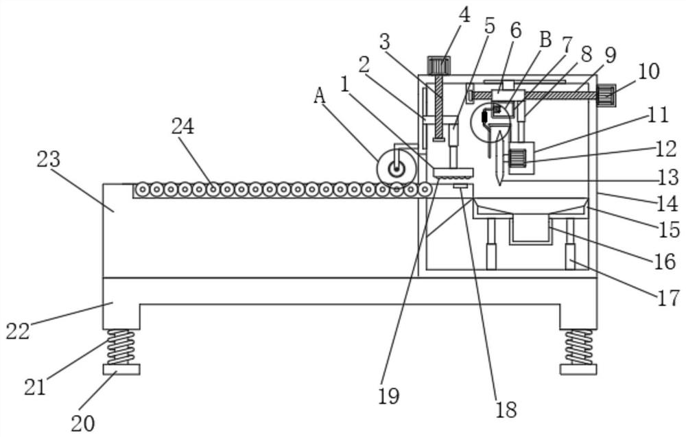
[0027] refer to Figure 1-5 , a cutting device for acrylic plate production, comprising a base 22, one side of the top outer wall of the base 22 is provided with a feeding table 23, and the other side of the top outer wall of the base 22 is provided with a working box 14, the feeding table 23 The outer wall of the top is provided with a groove, and the inner wall of the groove is connected with rollers 24 distributed equidistantly through bearings, and the outer wall of one side of the working box 14 is fixed with a mounting frame 28 by screws, and the outer wall of one side of the mounting frame 28 is provided with a servo motor 30. The output shaft of the servo motor 30 is connected to the driving roller 29 through a coupling, the top outer wall of the working box 14 is provided with a first motor 4, and the output shaft of the first motor 4 is connected to the first screw rod 3 through a coupling The outer wall of the first screw rod 3 is sleeved with a sliding plate 2, and...
Embodiment 2
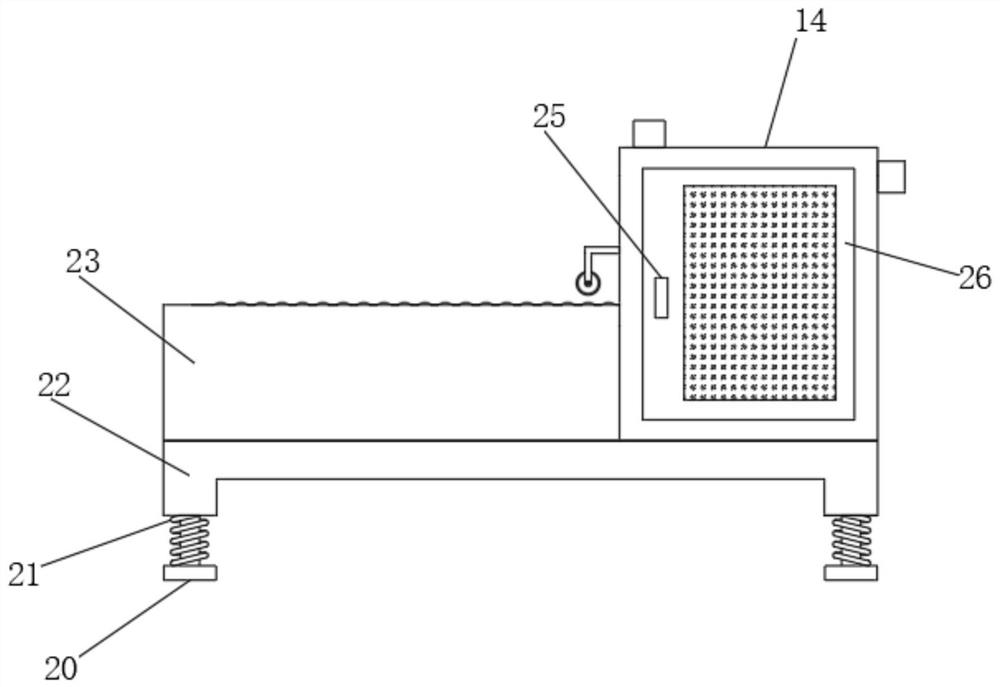
[0036] refer to figure 1 , a cutting device for the production of acrylic boards. Compared with Embodiment 1, this embodiment also includes a buffer hole on the bottom outer wall of the base 22, and a damping rod is slidably connected to the inner wall of the buffer hole, and the outer wall of the damping rod The damping spring 21 is sleeved, and the bottom end of the damping rod is provided with a support plate 20 .
[0037] The shock-absorbing spring 21 can have a good shock-absorbing effect, can reduce the noise generated when the device works, and creates a quiet production environment.
PUM
 Abstract
Description
Claims
Application Information
 - R&D Engineer
- R&D Manager
- IP Professional
- Industry Leading Data Capabilities
- Powerful AI technology
- Patent DNA Extraction
Browse by: Latest US Patents, China's latest patents, Technical Efficacy Thesaurus, Application Domain, Technology Topic, Popular Technical Reports.
© 2024 PatSnap. All rights reserved.Legal|Privacy policy|Modern Slavery Act Transparency Statement|Sitemap|About US| Contact US: help@patsnap.com