Anoxic tank gas stirring device for sewage treatment and stirring method

A technology of sewage treatment and air agitation, which is applied in the direction of biological water/sewage treatment, water/sludge/sewage treatment, water treatment parameter control, etc. It can solve the problems of insufficient mixing of sludge and water, excessive dissolved oxygen in anoxic pools, Unsatisfactory treatment effect and other problems, to achieve the effect of solving the dissolved oxygen exceeding the standard, good stirring effect, and improving the treatment effect

Pending Publication Date: 2020-12-04
QINHUANGDAO TONGLIDA WATER TREATMENT EQUIP
View PDF0 Cites 0 Cited by
  • Summary
  • Abstract
  • Description
  • Claims
  • Application Information

AI Technical Summary

Problems solved by technology

[0003] The purpose of the present invention is to aim at the prior art, when the gas stirring device is used to stir the anoxic pool, it is easy to cause the dissolved oxygen in the anoxic pool to exceed the standard, and the gas can only be stirred vertically, and t

Method used


Image

  • Anoxic tank gas stirring device for sewage treatment and stirring method
  • Anoxic tank gas stirring device for sewage treatment and stirring method
  • Anoxic tank gas stirring device for sewage treatment and stirring method

Examples


Example Embodiment

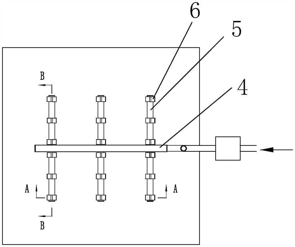
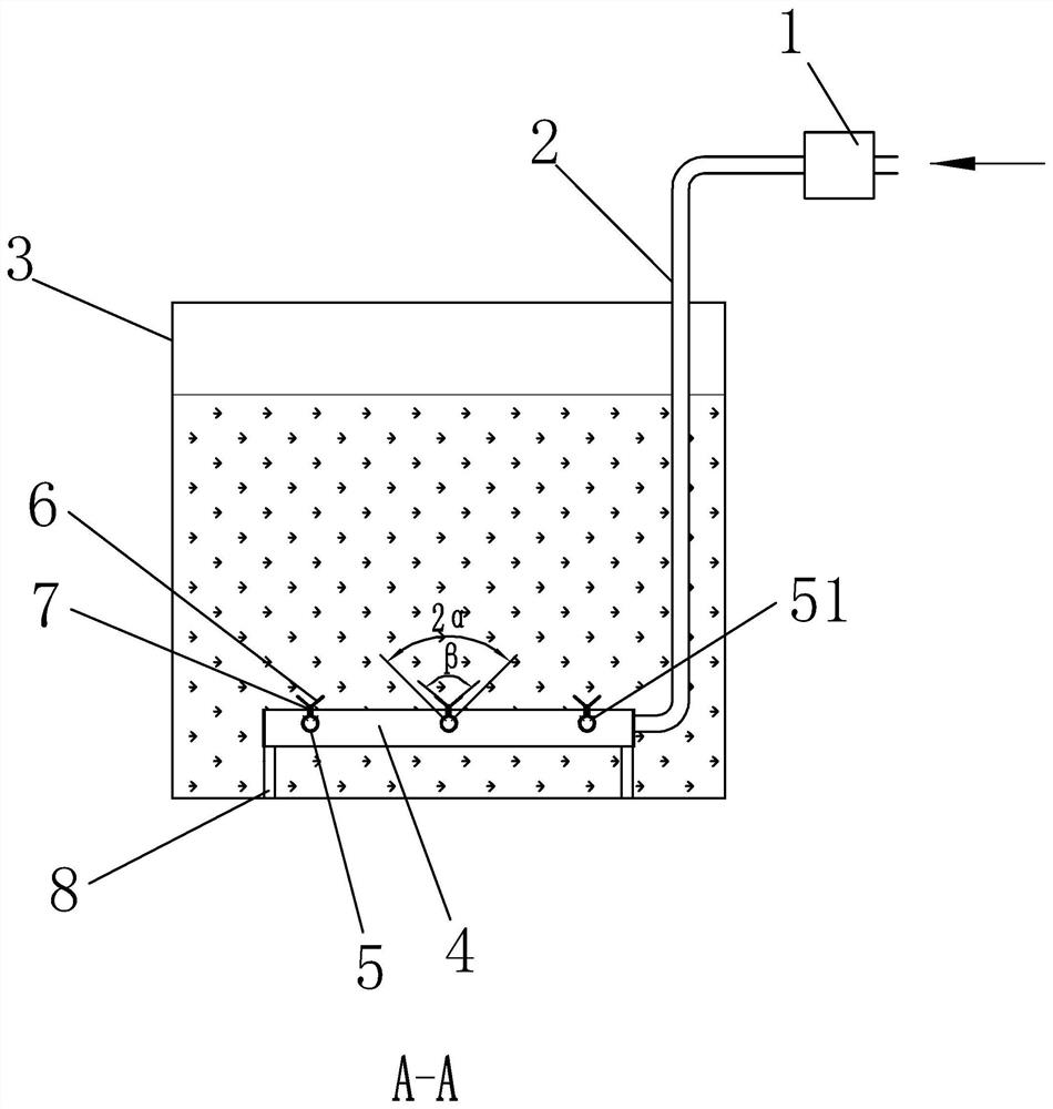
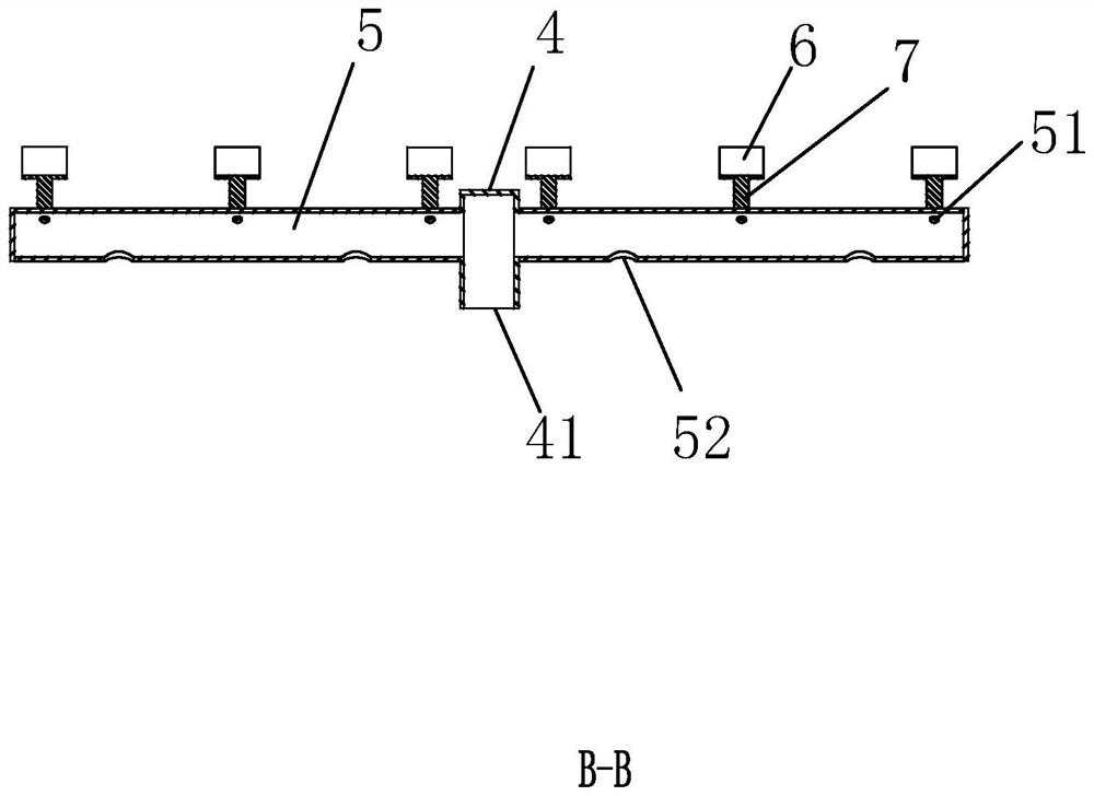
[0032]Embodiment 1: It includes a main pipe 4 and a branch pipe 5. The main pipe 4 is preferably a rectangular pipe. One end of the main pipe 4 communicates with the intake pipe 2 and the other end is closed. The branch pipes 5 are horizontally arranged on both sides of the main pipe 4. One end communicates with the main pipe 4 and the other end is closed. . A plurality of branch pipes 5 can be arranged on each side of the main pipe 4, and the branch pipes 5 on both sides can be staggered or arranged symmetrically. The axis of the branch pipes 5 and the main pipe 4 can be vertical or inclined at a certain angle. -500mm, the exhaust hole 51 can be arranged on the main pipe and the branch pipe, preferably only on the branch pipe 5. The main pipe and the branch pipe can be arranged in a straight line, a curve, a broken line, etc. respectively.

Example Embodiment

[0033] Embodiment two: if Figure 4 As shown, an annular pipe 9 is included, and the annular pipe 9 communicates with the intake pipe 2 . A connecting pipe piece 91 is arranged in the annular space of the annular pipe, and the two ends of the communicating pipe piece communicate with the annular pipe respectively. The annular pipe can be a rectangular ring, a circular ring or an elliptical ring, preferably the annular pipe 9 is a rectangle, and the annular space of the annular pipe is preferably evenly divided by the connecting pipe fitting 91, and the exhaust hole 51 is arranged on the annular pipe 9 and the connecting pipe fitting 91 . One or more connecting pipes 91 can be provided. When multiple connecting pipes are provided, the connecting pipes can be parallel to each other or intersect in a grid shape. The distance between the connecting pipes is preferably 300-1000mm.

[0034] Of course, when the annular pipe is included, multiple annular pipes can also be arranged ...


PUM


Abstract

In order to solve the problems that in the prior art, when a gas stirring device is adopted for stirring an anoxic tank, dissolved oxygen is prone to exceeding the standard, only vertical stirring isadopted, dead zones are prone to being generated, and sludge and water are not fully mixed, the invention provides the anoxic tank gas stirring device for sewage treatment and a stirring method. The device includes a closed gas stirring pipe, exhaust holes with upward openings are formed in the pipe wall, guide pieces are obliquely arranged above the exhaust holes, gas exhausted from the exhaust holes generates transverse and longitudinal movement directions under the action of the guide pieces, the gas moving transversely and longitudinally drives water flow to move transversely and longitudinally, the water flow is interwoven,and a dead zone of vertical stirring is eliminated. According to the anoxic tank gas stirring device provided by the invention, the mixing degree of sludge and water is enhanced, the sewage treatment effect is improved, the stirring method provided by the invention guides gas to move transversely and longitudinally and intermittently supplies gas to the gas stirring pipe, a good stirring effect is achieved by using less gas, and the dissolved oxygen content is reduced.

Description

technical field [0001] The invention relates to the technical field of sewage treatment, in particular to an anoxic pool gas stirring device and a stirring method for sewage treatment. Background technique [0002] At present, in the domestic integrated treatment equipment, the biochemical part of sewage treatment is mainly divided into anaerobic pool, anoxic pool, and aerobic pool. Stirring is required. The dissolved oxygen content in the anoxic pool is 0.2-0.5mg / L. During sewage treatment, mechanical stirring devices and gas stirring devices are usually used to stir the water in the anoxic pool. When mechanical stirring devices are used for stirring, submersible stirring is generally used. However, due to the small volume of the integrated equipment pool, there is no matching small submersible mixing equipment on the market. The rated power of the existing mixing equipment is much higher than the use requirements. Unnecessary power consumption, high cost of movement, hig...

Claims


Application Information

Patent Timeline
IPC IPC(8): C02F3/28B01F13/02B01F33/40
CPCC02F3/28C02F3/2833C02F2209/22B01F33/401B01F33/4094
Inventor 罗林宋绍男
Owner QINHUANGDAO TONGLIDA WATER TREATMENT EQUIP
Why Eureka
Try Eureka