
Novel valve hall plugging structure and fire resistance checking method

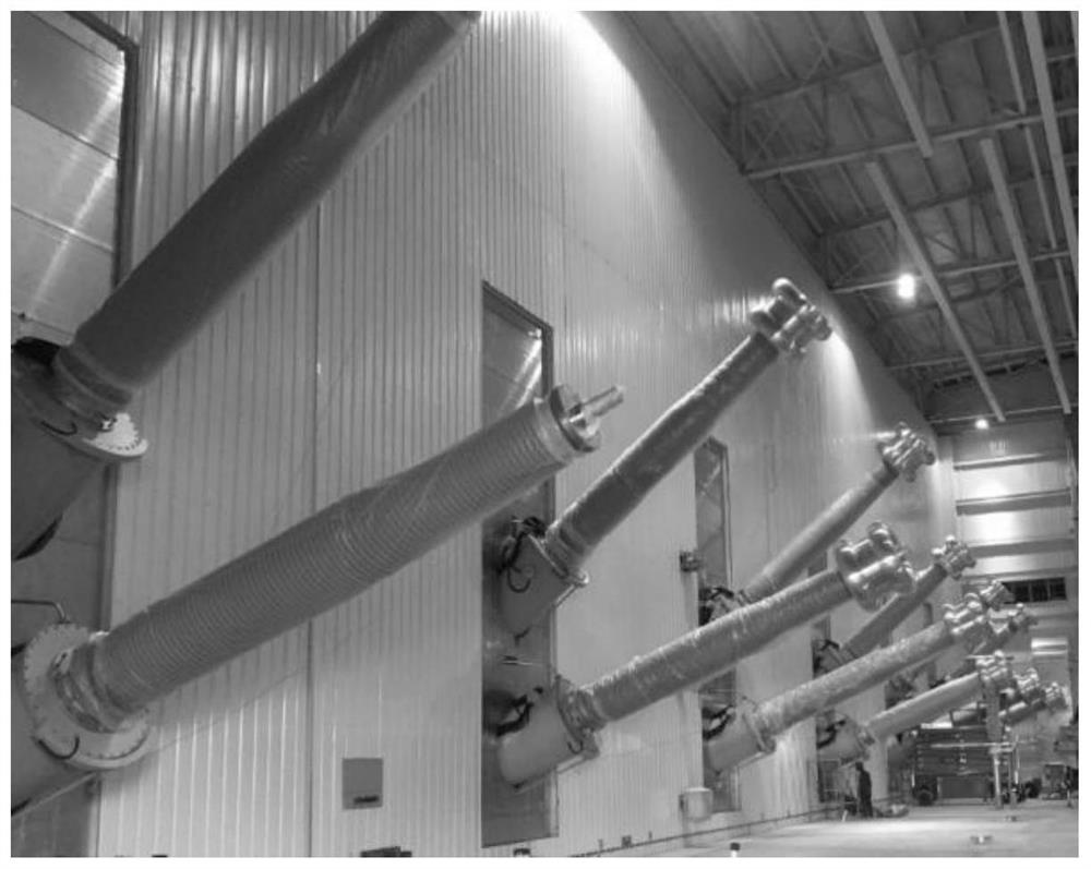
A new type of structure and valve hall technology, which is applied in fire protection, building components, building structures, etc., can solve the problems of not having special anti-explosion force, inability to resist low explosion impact force, and loss of fire prevention ability of single-layer fire-proof board structure, etc. To achieve the effect of improving thermal insulation performance, strong shock resistance, and ensuring thermal insulation performance

Inactive Publication Date: 2020-12-04
EXAMING & EXPERIMENTAL CENT OF ULTRAHIGH VOLTAGE POWER TRANSMISSION COMPANY CHINA SOUTHEN POWER GRID +1
View PDF8 Cites 1 Cited by
  • Summary
  • Abstract
  • Description
  • Claims
  • Application Information

AI Technical Summary

Problems solved by technology

[0004] At present, the original single-layer fireproof panel structure does not have a special anti-explosion structure. It has also been shown in actual fire cases that the current single-layer fireproof panel structure cannot resist these explosion impact forces.
These explosions usually occur at the same time as the converter fire, so the single-layer fireproof panel structure may be damaged by the explosive force and lose its fireproof ability when the fire occurs

Method used


Image

  • Novel valve hall plugging structure and fire resistance checking method
  • Novel valve hall plugging structure and fire resistance checking method
  • Novel valve hall plugging structure and fire resistance checking method

Examples


Embodiment

[0045] It is to be understood that the terms "center", "longitudinal", "transverse", "length", "width", "thickness", "upper", "lower", "front", "rear", "left", "Right", "Vertical", "Horizontal", "Top", "Bottom", "Inner", "Outer", "Clockwise", "Counterclockwise", "Axial", "Radial", " The orientation or positional relationship indicated by "circumferential direction" is based on the orientation or positional relationship shown in the drawings, and is only for the convenience of describing the present invention and simplifying the description, rather than indicating or implying that the referred device or element must have a specific orientation, Constructed and operative in a particular orientation and therefore should not be construed as limiting the invention.

[0046] In addition, the terms "first" and "second" are used for descriptive purposes only, and cannot be interpreted as indicating or implying relative importance or implicitly specifying the quantity of indicated tech...


PUM

PropertyMeasurementUnit
Diameteraaaaaaaaaa

Abstract

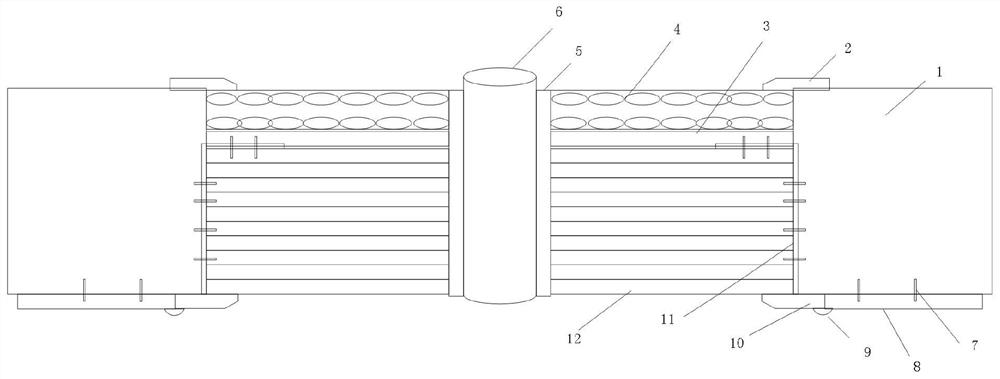
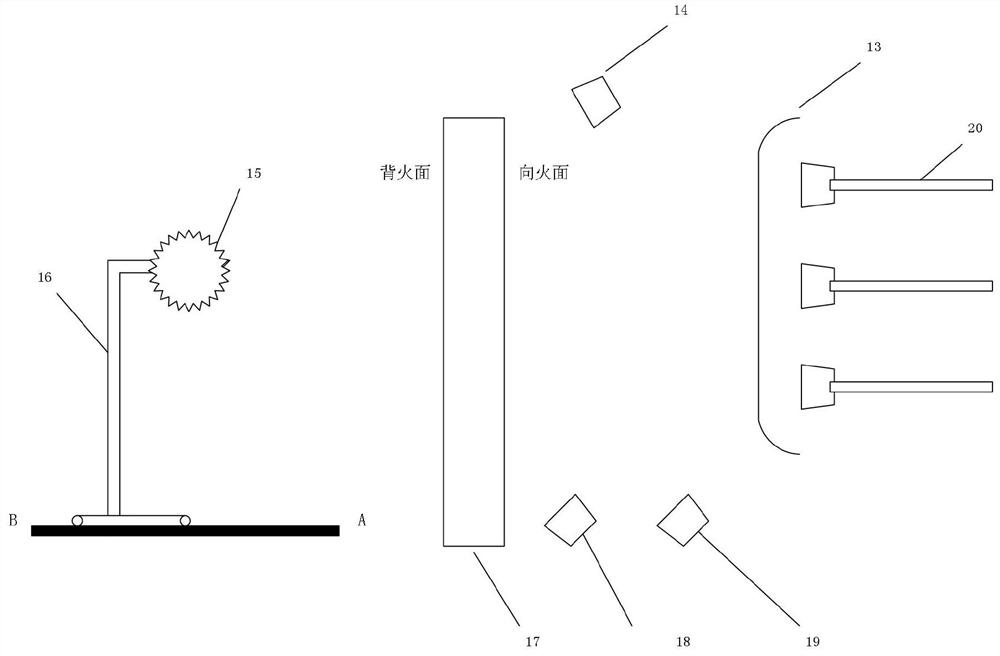
The invention discloses a novel valve hall plugging structure and a fire resistance checking method, and relates to the field of direct-current power transmission. The structure is used for enhancingthe fire resistance and explosion resistance of a firewall between a converter transformer and a valve hall; the structure comprises a first plug and a second plug, a converter transformer sleeve on the converter transformer side penetrates through the first plug and extends to the valve hall side, and the second plug is arranged on the contact surface of the converter transformer sleeve and the first plug; the first plug is sequentially connected with a buffer energy absorption layer, an explosion-proof steel plate layer and a fireproof layer from the converter transformer side to the valve hall side; and the second plug comprises a ceramic silicone rubber waterproof sealing sleeve used for being arranged on the converter transformer sleeve in a sleeving mode and an aluminum silicate fiber needled blanket arranged between the contact faces of the converter transformer sleeve and the first plug in a filling mode. The method is used for checking the fire resistance of the structure. Thestructure can not deform or fail under the severe high-temperature combustion condition, and therefore valve hall equipment is protected against damage under the adverse condition that a transformerexplodes and is on fire.

Description

technical field [0001] The invention relates to the field of direct current transmission, in particular to a novel valve hall sealing structure and a fire resistance checking method. Background technique [0002] The converter substations are arranged adjacent to the valve hall, and a firewall is set between the converter substation and the valve hall, and the valve side bushing of the converter converter is inserted into the valve hall through the opening on the firewall. After the converter transformer is installed in place, the opening needs to be sealed to meet the operating requirements of the valve hall. [0003] The active fire of the converter is usually caused by the temperature rise of the internal fault of the converter, especially the arc heating, the temperature can reach thousands of degrees, and the insulating oil is cracked into combustible gas. Large stress is formed inside the rheological oil tank body, which causes the oil-filled shell of the rheological ...

Claims


Application Information

Patent Timeline
IPC IPC(8): E04H5/04E04B1/94E04B1/98G01N25/22G01S17/88G01D21/02
CPCE04B1/94E04B1/941E04B1/942E04B1/98E04H5/04G01D21/02G01N25/22G01S17/88
Inventor 邓军潘志城邓集瀚谢志成梁晨刘青松张晋寅周海滨
Owner EXAMING & EXPERIMENTAL CENT OF ULTRAHIGH VOLTAGE POWER TRANSMISSION COMPANY CHINA SOUTHEN POWER GRID
Learn More