A Span Asymmetric Pit Gas Film Cooling Pass

A film cooling, asymmetric technology, applied in the direction of climate sustainability, blade support components, sustainable transportation, etc., can solve the problems of low cooling efficiency, difficult processing, easy blowing of cold air jets off the blade surface, etc., to achieve The effect of increasing the area, increasing the spanwise width, and increasing the spanwise coverage area of ​​the gas film

Active Publication Date: 2022-08-09
TIANJIN UNIVERSITY OF TECHNOLOGY
View PDF4 Cites 0 Cited by
  • Summary
  • Abstract
  • Description
  • Claims
  • Application Information

AI Technical Summary

Problems solved by technology

The structure of the cylindrical hole is simple, but the high momentum of the cold air at a high blowing ratio makes the cold air jet easy to blow off the blade surface, especially in the far downstream surface cooling efficiency is low
Compared with the cylindrical pass, the outlet expansion pass greatly improves the cooling efficiency, but its processing is more difficult

Method used


Image

  • A Span Asymmetric Pit Gas Film Cooling Pass
  • A Span Asymmetric Pit Gas Film Cooling Pass
  • A Span Asymmetric Pit Gas Film Cooling Pass

Examples


Embodiment 1

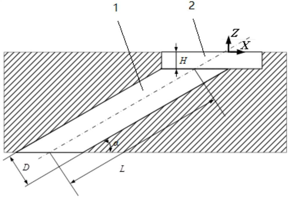
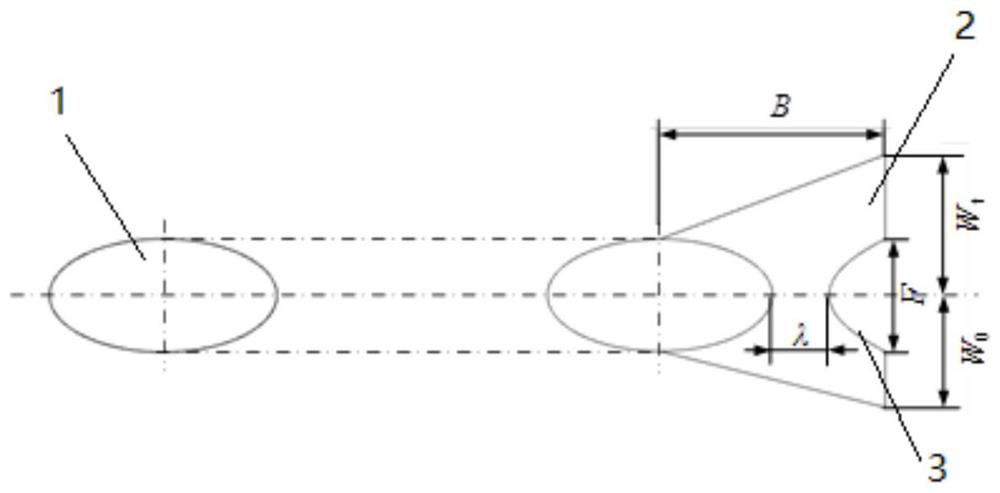
[0024] Embodiment 1: In the first embodiment of the present invention, there is provided a spanwise asymmetrical dimple gas film cooling hole structure that increases the spanwise expansion width of the downstream side of the vertical cross flow in the dimple expansion structure 2, Figure 2-1 , Figure 2-2 It is the geometrical structure diagram of the air-film cooling hole type of the spanwise asymmetric pit in Example 1 of the present invention. like Figure 2-1 As shown, the spanwise asymmetric pit structure is a pit expansion structure 2 that expands asymmetrically along the spanwise direction from both sides of the outlet of the cylindrical hole 1. W t Indicates that the spanwise expansion width of the upstream side of the internal cooling vertical cross flow is defined by W 0 express, W t / W 0 =1.25 is the main feature of this spanwise asymmetrical pit gas film cooling pass pattern Example 1 which is different from the original spanwise symmetrical pit gas film...

Embodiment 2

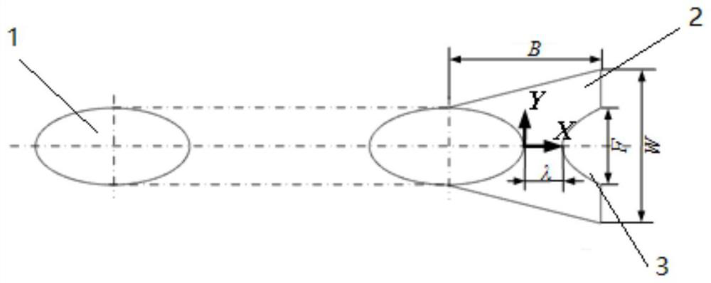
[0027] Embodiment 2: In the second embodiment of the present invention, a spanwise asymmetrical dimple gas film cooling hole structure is provided by offsetting the expansion-shaped boss at the downstream gas outlet of the dimple structure, Figure 3-1 , Figure 3-2 It is a structural diagram of Embodiment 2 of the present invention. The spanwise asymmetric pit structure has an arc-shaped expansion boss 3 on the gas outlet side of the pit, and the boss 3 is offset to the downstream side of the internal cooling vertical cross flow. The position of the expanded boss 3 presents an asymmetric distribution in the spanwise direction, which is the main feature of the second embodiment of the present invention that is different from the original spanwise symmetrical pit gas film cooling hole pattern. The front end of the boss 3 and the cylindrical hole 1 flow between the center line spanwise offset distance of K spanwise width with boss 3 F ratio K / F= 0.25.

[0028] In Example ...


PUM


Abstract

A spanwise asymmetric pit gas film cooling hole pattern, which is used for cooling gas turbine turbine blades, especially turbine moving blades, is characterized in that: the gas film cooling hole pattern is based on a cylindrical hole, and the cylindrical hole exits There is a spanwise asymmetric pit structure along the spanwise direction of the centerline of the cylindrical hole. The invention obtains an asymmetrical air film cooling structure of the pit by adjusting the depth of the pit structure, increasing the expansion width of the downstream side of the vertical cross flow of the pit structure, and moving the boss to the downstream side of the inner cooling vertical cross flow. Increase the spanwise width of the outlet side of the downstream side of the internal cooling vertical cross flow, and reasonably adjust the spanwise position of the boss to effectively block the high-momentum cooling jet on the downstream side of the internal cooling vertical cross flow and reduce the height of the cold air injected into the mainstream, so as to solve the problem. The problems of uneven spanwise distribution of the cooling jet under the condition of vertical internal cooling and cross flow, and low cooling efficiency.

Description

technical field [0001] The invention relates to the technical field of gas turbine turbine cooling, in particular to a spanwise asymmetrical dimple gas film cooling hole pattern. Background technique [0002] A gas turbine is a widely used heat engine device, which generates power by pushing the turbine to do work by expanding the high-temperature and high-pressure gas obtained after combustion in a combustion chamber. With the continuous improvement of the output power and efficiency requirements of gas turbines, the inlet temperature of the turbine has far exceeded the temperature limit of the current nickel-based metal blade material. Therefore, effective cooling technology must be used to reduce the thermal load of the turbine blade and ensure that the gas Safe operation of the turbine. [0003] Air film cooling is an efficient external blade cooling measure. The cold air from the cooling chamber inside the turbine blade flows out through discrete air film holes and cov...

Claims


Application Information

Patent Timeline
Patent Type & Authority Patents(China)
IPC IPC(8): F01D5/18
CPCF01D5/186Y02T50/60
Inventor 张超白林超童志庭石淯臣
Owner TIANJIN UNIVERSITY OF TECHNOLOGY
Why Eureka
Try Eureka