Vacuum Liquid Injection Method and Device for Copper Tube Radiator

A heat sink and copper tube technology, which is applied in the field of copper tube heat sink vacuum liquid injection method and its device, can solve the problems that it is difficult to enter the copper tube cavity, the amount of injection is difficult to grasp, and the operation is difficult, so that the injection volume is small, Improve the output speed and reduce the difficulty of operation

Active Publication Date: 2022-05-27
FOSHAN YOUBA MASCH EQUIP CO LTD
View PDF0 Cites 0 Cited by
  • Summary
  • Abstract
  • Description
  • Claims
  • Application Information

AI Technical Summary

Problems solved by technology

[0003] At present, the most critical step in the production process of commonly used copper tube heat sinks for mobile phones is to inject refrigerant. Generally speaking, water is used as the refrigerant. Because the copper tubes used for heat dissipation are small in size, it is often difficult to inject water and after injection. In order to solve this problem, the general method is to inject a part of water into the copper tube first, and then use high-pressure gas to press the water into the copper tube. However, this method is more difficult to operate. , and the injection volume is very limited

Method used


Image

  • Vacuum Liquid Injection Method and Device for Copper Tube Radiator
  • Vacuum Liquid Injection Method and Device for Copper Tube Radiator
  • Vacuum Liquid Injection Method and Device for Copper Tube Radiator

Examples


Embodiment Construction

[0031] The embodiments of the present invention will be described below with reference to the accompanying drawings and related embodiments. It should be noted that the following related embodiments are only preferred embodiments for better illustrating the present invention, and the embodiments of the present invention are not limited to In the following embodiments, and the present invention relates to the relevant necessary components in the technical field, it should be regarded as a well-known technology in the technical field, which can be known and mastered by those skilled in the technical field.

[0032] In the description of the present invention, it should be understood that the terms "lateral", "upper", "lower", "front", "rear", "left", "right", "vertical", "horizontal", The orientation or positional relationship indicated by "in" and the like is based on the orientation or positional relationship shown in the drawings, and is only for the purpose of sub-description...


PUM


Abstract

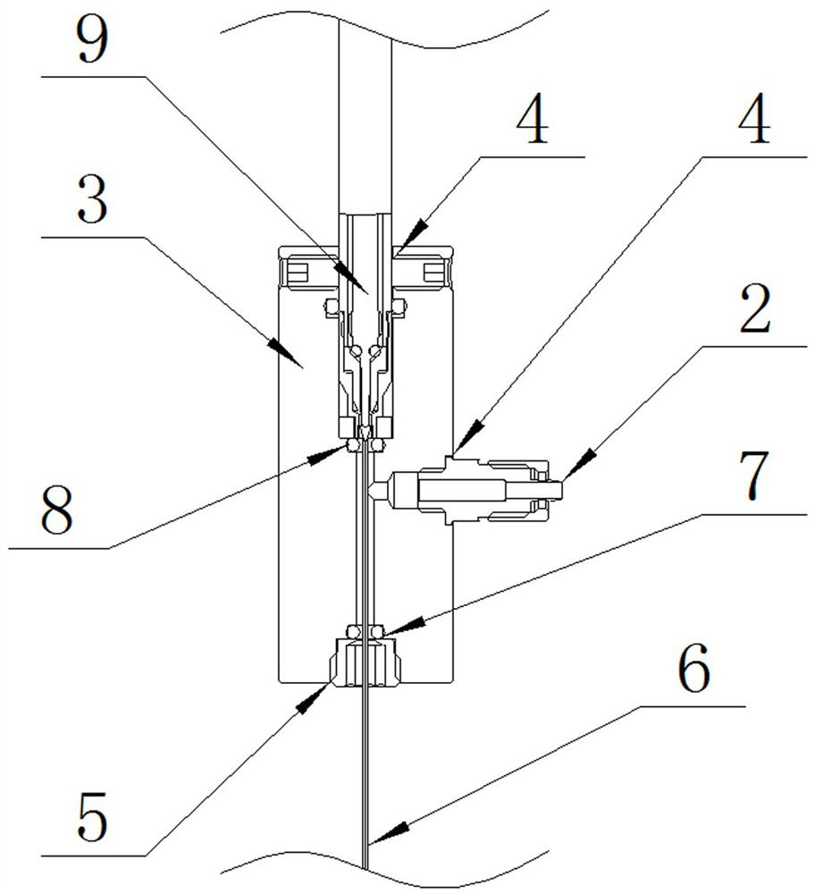
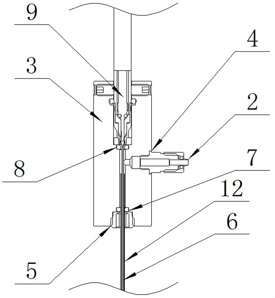
The present invention relates to a vacuum liquid injection method for a copper tube heat sink and a device thereof, comprising the following steps: Step 1, a liquid injection pipe is partially inserted into a copper tube heat sink; Step 2, while closing a liquid injection path, open a vacuum pumping path and evacuate; 3. The liquid injection pipe is fully inserted, and the vacuuming passage is closed; step 4, the liquid injection passage is opened, and the refrigerant is injected; step 5, the copper tube heat sink is physically closed; step 6, the copper pipe heat sink is removed, and the completion Liquid injection, wherein the device includes a liquid injection valve, a vacuum valve circuit and a T-shaped pump nozzle part, and the T-shaped pump nozzle part is provided with a valve interface and a liquid injection interface perpendicular to each other. The beneficial effects of the present invention are: using The principle of vacuum negative pressure reduces the difficulty of liquid injection, and the refrigerant can be effectively injected into the cavity of the copper tube heat sink. The single injection volume is extremely small, the injection volume is accurate, and the operation difficulty is low. It can be well adapted to the copper tube heat sink for mobile phones. , to ensure the production efficiency and production quality of the product.

Description

technical field [0001] The invention belongs to the technical category of copper tube heat sink production, and specifically relates to a copper tube heat sink vacuum injection method and device thereof. Background technique [0002] Copper tube heat sinks are a wide range of component fields and are widely used in many machines and equipment that require heat exchange or simply cooling. Among them, the volume of copper tube heat sinks used in smartphones It belongs to the smallest batch in comparison, so its production method is different from the existing conventional copper tube fins or copper tube radiators. [0003] At present, a very critical step in the production process of commonly used copper tube heat sinks for mobile phones is to inject refrigerant. Generally speaking, water is used as the refrigerant. Due to the small volume of copper tubes used for heat dissipation, it is often difficult to inject water and difficult to inject after injection. In order to solv...

Claims


Application Information

Patent Timeline
Patent Type & Authority Patents(China)
IPC IPC(8): F28D15/04
CPCF28D15/04F28D15/0283
Inventor 黄锦成黎昕明
Owner FOSHAN YOUBA MASCH EQUIP CO LTD
Why Eureka
Try Eureka