Disc body drilling machine for floor sweeping disc machining

A technology of drilling machine and drilling mechanism, which is applied in the direction of metal processing machinery parts, boring/drilling, metal processing equipment, etc., can solve the problems of difficult calculation and increase the difficulty of calculating the drilling trajectory of automation equipment, and achieve improvement Efficiency, high superiority and creativity, simple effect of moving track programming process

Inactive Publication Date: 2020-12-08
安徽省玉环清洗设备制造有限公司
View PDF10 Cites 12 Cited by
  • Summary
  • Abstract
  • Description
  • Claims
  • Application Information

AI Technical Summary

Problems solved by technology

[0004] However, the above-mentioned device is used to adjust the angle of the brush plate. After the angle adjustment of the brush plate is completed each time, the drilling position of the brush plate also changes. At this time, it is necessary to precisely control the position of the drilling equipment before proceeding to the next position. For drilling holes, give an example: the existing brush discs, the brush filament holes on it all gradually expand the inclination angle around the center of the disc body (as attached Figure 5 As shown), if the above-mentioned device is used for multi-angle drilling, such a problem will inevitably occur, that is, every time an angle is adjusted, the next drilling position becomes more difficult to calculate. Nowadays, automatic equipment is commonly used for drilling. This adjustment method will inevitably increase the difficulty of calculating the punching trajectory of the automation equipment

Method used


Image

  • Disc body drilling machine for floor sweeping disc machining
  • Disc body drilling machine for floor sweeping disc machining
  • Disc body drilling machine for floor sweeping disc machining

Examples


Embodiment Construction

[0021] The technical solutions in the embodiments of the present invention will be clearly and completely described below with reference to the accompanying drawings in the embodiments of the present invention. Obviously, the described embodiments are only a part of the embodiments of the present invention, but not all of the embodiments. Based on the embodiments of the present invention, all other embodiments obtained by those of ordinary skill in the art without creative efforts shall fall within the protection scope of the present invention.

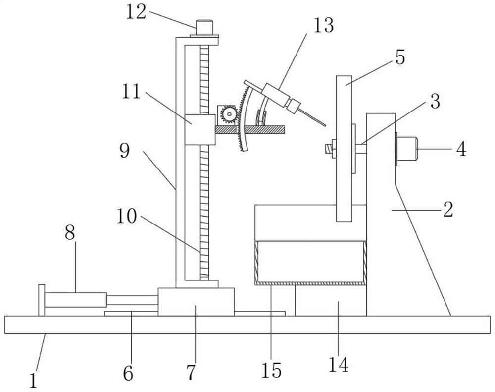
[0022] See attached Figures 1 to 5 , the present invention provides a technical solution: a disk drilling machine for sweeping disk processing, comprising a bottom plate 1, a fixing frame 2 is arranged on the right side of the top end of the bottom plate 1, and a mounting shaft is provided on the upper side of the fixing frame 2 for lateral rotation. 3. The right end of the installation shaft 3 is connected with the rotating motor 4,...


PUM


Abstract

The invention discloses a disc body drilling machine for floor sweeping disc machining, and belongs to the technical field of floor sweeping disc machining. The disc body drilling machine comprises abottom plate; and a fixing frame is arranged on the right side of the top end of the bottom plate. An arranged multi-angle drilling mechanism takes an initial position of a drill bit as a fixed pointand the fixed point as the circle center, a drill rod rotates around the fixed point through a mechanical transmission mechanism to complete adjustment of the drilling angle, during drilling, the drill rod can be moved to the next drilling path through a lifting mechanism by calculating the radius difference of annular brush wire holes in a brush disc, therefore the movement track programming process of the drill rod becomes extremely simple, and the disc body drilling machine is quite suitable for modern automatic production equipment; when the drilling angle is adjusted and the drill rod ismoved to the corresponding drilling path, a mounting shaft can drive a brush disc body to rotate, and therefore the drilling process of brush wire holes in the same annular path can be completed in sequence, so that the multi-angle hole punching efficiency is greatly improved; and it can be seen that the angle adjusting mode of the disc body drilling machine has extremely high superiority and creativity.

Description

technical field [0001] The invention relates to the technical field of sweeping disk processing, in particular to a disk body drilling machine for sweeping disk processing. Background technique [0002] Disc brushes are one of the more commonly used tools in the field of sanitation. They are mainly composed of brush discs and brush wires embedded in the brush discs. During the production process of brushes, the brush wires are usually inserted into the sockets on the brush disc. , fixed by pressing, bundling, cutting, etc. In the prior art, the production of brush discs is mostly made of plastic plates, which are cut into disc shapes, and then a series of circular holes are processed by drilling equipment. The fixed inclination angle is fixed, so that the vertical circular holes or inclined circular holes parallel to each other at the punching place have single function and poor flexibility, which cannot meet the production needs of sockets with various inclination angles f...

Claims


Application Information

Patent Timeline
Patent Type & Authority Applications(China)
IPC IPC(8): B23B41/00B23B47/20B23B47/22B23Q3/06
CPCB23B41/00B23Q3/06B23Q5/22B23Q5/28
Inventor 游奕明
Owner 安徽省玉环清洗设备制造有限公司
Why Eureka
Try Eureka