Channel steel-concrete composite beam and manufacturing method thereof

A technology of concrete and channel steel, applied in bridges, bridge parts, bridge materials, etc., can solve the problems of heavy welding workload and low bearing capacity of composite beams, and achieve the effect of strong bearing capacity, simple structure and high connection strength

Active Publication Date: 2020-12-08
HUNAN INST OF TECH
View PDF7 Cites 0 Cited by
  • Summary
  • Abstract
  • Description
  • Claims
  • Application Information

AI Technical Summary

Problems solved by technology

Connectors, as the key stress-bearing components that make steel beams and concrete bridge slabs a whole, generally need to be welded with steel beams, and the quality of welds between connectors and steel beams will affect the stress and safety of the entire composite beam structure , there are strict requirements for the welding process, and the welding workload is relatively large
[0004] Chinese patent document CN109537453A discloses a channel-shaped steel-concrete composite beam. The steel-concrete composite beam has the following defects in structure: 1. The steel beam only limits the degrees of freedom in the front, back and down directions of the steel bar, and the steel bar cage The vertical upward direction is only limited by the adhesive force of concrete, and the bearing capacity of the entire composite beam is low

Method used


Image

  • Channel steel-concrete composite beam and manufacturing method thereof
  • Channel steel-concrete composite beam and manufacturing method thereof
  • Channel steel-concrete composite beam and manufacturing method thereof

Examples


Embodiment 1

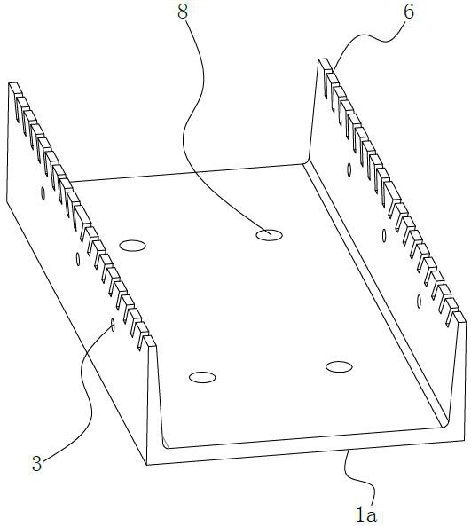
[0046] See Figure 1-2 As shown, in this embodiment, the oblique notch 6 is set at the top of the side plate of the outer beam 1a, and correspondingly, the vertical notch 7 is set at the top of the side plate of the inner beam 1b, and is located at the oblique front half of the side plate of the outer beam 1a. The direction of inclination toward the notch 6 is not the same as that of the oblique notch 6 located at the rear half of the side plate.

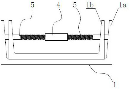
[0047] Further, in this embodiment, see Figure 3-5 , the threaded sleeve 4 is hexagonal as a whole, and the advantage of designing the threaded sleeve 4 as a hexagonal prism is: firstly, it can be easily screwed, and secondly, after the threaded sleeve 4 is wrapped by concrete, it can better prevent threading Socket 4 is loose. Wherein, a screw hole is provided along the axial direction of the threaded sleeve 4, and the threaded sleeve 4 is fixedly connected with the serial ribs 5 located on the left and right sides through the s...

Embodiment 2

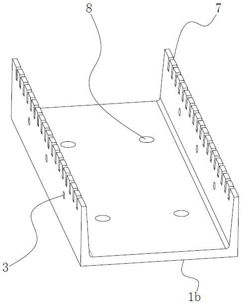
[0052] See Figure 6 and Figure 7 As shown, the difference between this embodiment and Embodiment 1 is that the top end of the side plate of the inner beam 1b is lower than the top end of the side plate of the outer beam 1a, so that the vertical notch 7 at the top of the side plate of the inner beam 1b can be opened The depth is designed to be equal to the diameter of the reinforcing bar 2a or slightly darker than the diameter of the reinforcing bar 2a, so that the reinforcing bar 2a is placed. The structure of other parts of this embodiment and the manufacturing method of the composite beam are similar to those of Embodiment 1, and will not be repeated here.

Embodiment 3

[0054] See Figure 8 As shown, the difference between this embodiment and Embodiment 1 is mainly that the vertical notch 7 is set at the top of the side plate of the outer beam 1a, and the oblique notch 6 is set at the top of the side plate of the inner beam 1b. The structure of other parts of this embodiment and the manufacturing method of the composite beam can also be similar to that of Embodiment 1. It should be noted that in this embodiment, the oblique notch 6 is not limited to Figure 8 In the opening method shown, on the premise that the oblique notches 6 are opened at the top of the side plate of the inner girder 1b, it is actually a better solution to make all the oblique notches 6 have the same inclination direction, so that the bridge deck 2 is thicker and It will be more convenient for construction and installation when a built-in steel cage is required. The specific construction method is as follows: firstly, the inner beam 1b and the outer beam 1a are made res...


PUM


Abstract

The invention relates to a channel steel-concrete composite beam and a manufacturing method thereof, and belongs to the technical field of bridge engineering. The channel steel-concrete composite beamcomprises a steel beam and a bridge deck, wherein the steel beam comprises an outer beam and an inner beam which are made of large channel steel and small channel steel respectively; the inner beam is placed in a groove cavity of the outer beam, a bottom plate of the inner beam is abutted with a bottom plate of the outer beam, and series connection holes are respectively formed in side plates onthe left and right sides of the outer beam and the inner beam and are connected in series through series connection ribs; inclined notches and vertical notches which are in one-to-one correspondence are formed in the top ends of the side plates of the inner beam and the outer beam; and the bridge deck stretches across the steel beam, at least one part of steel bars at the bottom of the bridge deckpenetrate through the inclined notches and the vertical notches, and concrete of the bridge deck wraps the steel bars, the series connection bars and the top end of the steel beam, so that the steelbeam and the reinforced concrete bridge deck are connected into a whole. The channel steel-concrete composite beam has the advantages of the simple structure, no need of welding and high bearing capacity.

Description

technical field [0001] The invention relates to the technical field of bridge engineering, in particular to a channel-shaped steel-concrete composite beam and a manufacturing method thereof. Background technique [0002] A beam made of two different materials is called a composite beam, where the main girder is made of one material and the bridge deck connecting the main girder is made of another material. [0003] In the steel-concrete composite beam, the connector (shear key) is the key component that combines the steel beam and the reinforced concrete slab to jointly bear the force. Connectors, as the key stress-bearing components that make steel beams and concrete bridge slabs a whole, generally need to be welded with steel beams, and the quality of welds between connectors and steel beams will affect the stress and safety of the entire composite beam structure , there are strict requirements for the welding process, and the welding workload is relatively large. [000...

Claims


Application Information

Patent Timeline
Patent Type & Authority Applications(China)
IPC IPC(8): E01D19/12E01D2/00E01D101/26E01D101/30
CPCE01D19/125E01D2/00E01D2101/30E01D2101/26
Inventor 郭范波夏宇吴婷
Owner HUNAN INST OF TECH
Why Eureka
Try Eureka