Glass powder filling device for wafer manufacturing and using method thereof

A filling device and glass frit technology, applied in semiconductor/solid-state device manufacturing, electrical components, circuits, etc., can solve the problems of poor painting stability, high production cost, and low painting speed.

Inactive Publication Date: 2020-12-08
王丽丽
View PDF0 Cites 4 Cited by
  • Summary
  • Abstract
  • Description
  • Claims
  • Application Information

AI Technical Summary

Problems solved by technology

But the brushing speed of this method is low, thereby affecting the production speed of the product, the production cost of the product is high, and the quality of the glass powder brushing depends on the labor ability of the worker, and the stability of the brushing is relatively poor, resulting in electronic components The pass rate is low, which further increases the production cost of the product

Method used


Image

  • Glass powder filling device for wafer manufacturing and using method thereof
  • Glass powder filling device for wafer manufacturing and using method thereof
  • Glass powder filling device for wafer manufacturing and using method thereof

Examples


Embodiment 1

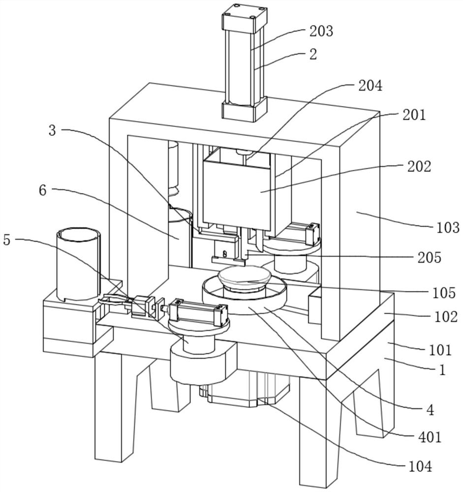
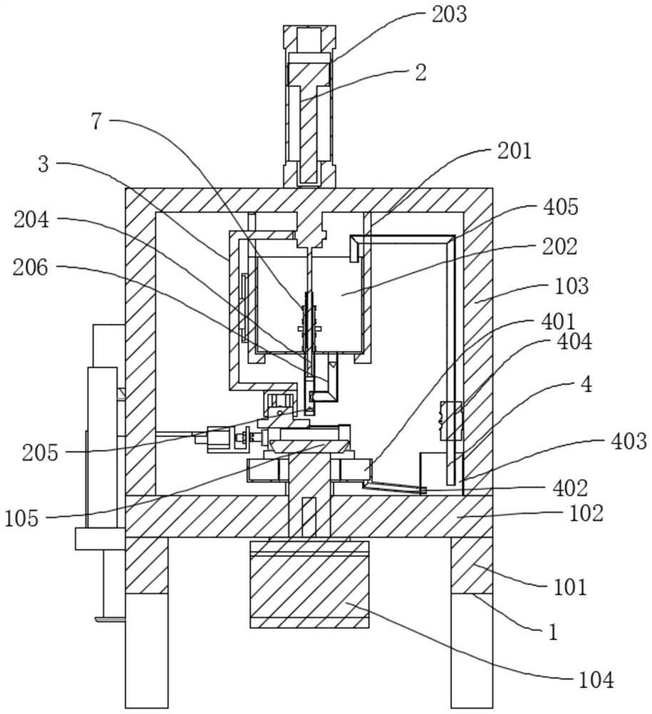
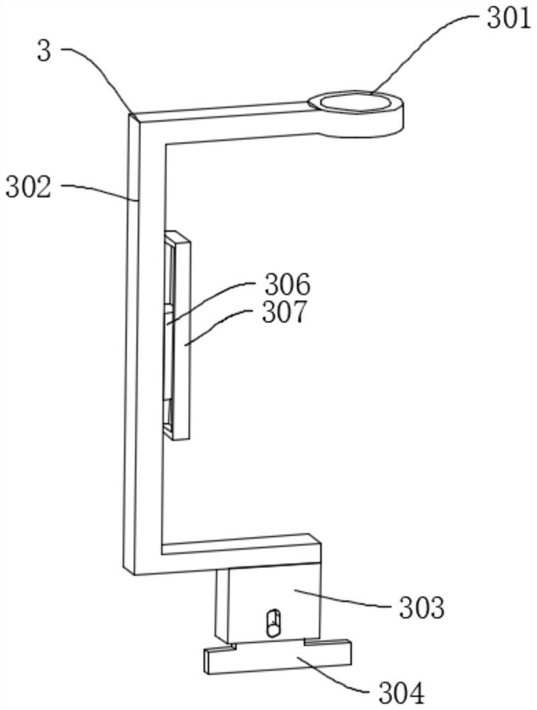
[0042] like Figure 1-7As shown, a glass powder filling device for wafer manufacturing includes a device body 1, a filling mechanism 2, an automatic feeding mechanism 5, and an automatic unloading mechanism 6. The device body 1 includes a support leg 101, a worktable 102, a machine A frame 103, a first motor 104, a wafer placement table 105, a worktable 102 is connected to the top of the support leg 101 by bolts, a frame 103 is connected to the top of the worktable 102 by bolts, a filling mechanism 2 is arranged inside the frame 103, and the worktable The center of the bottom of 102 is connected with a first motor 104 by bolts, the output end of the first motor 104 passes through the worktable 102, and is connected with a wafer placement table 105 by keys, and a recovery mechanism 4 is provided on the outer side of the bottom of the wafer placement table 105, so that The first motor 104 can drive the wafer placement stage 105 to rotate, and the wafer placement stage 105 drives...

Embodiment 2

[0050] like Figure 8-9 As shown, Embodiment 2 differs from Embodiment 1 in that: the blanking storage bucket 608 is connected above the blanking support plate 607 by bolts, and a drying assembly 609 is provided inside the blanking storage bucket 608, so that the drying assembly 609 The wafer is taken out from the inside of the blanking storage bucket 608. The drying assembly 609 includes a top plate 6091 and an ejector rod 6092. The upper end of the ejector rod 6092 passes through the blanking support plate 607 and is connected to the blanking support plate 607, and is welded with the top plate 6091 and the top plate. 6091 is located inside the unloading storage bucket 608. In this way, the ejector pin 6092 can be pushed, and the ejector pin 6092 drives the top plate 6091 to rise, and the top plate 6091 pushes the wafer, so that the wafer rises, so that the wafer is lifted from the inside of the unloading storage bucket 608. out.

[0051] A method for using a glass frit fill...


PUM


Abstract

The invention discloses a glass powder filling device for wafer manufacturing and a using method thereof. The glass powder filling device comprises a device body, a filling mechanism, an automatic feeding mechanism and an automatic discharging mechanism, the device body comprises supporting legs, a workbench, a rack, a first motor and a wafer placing table, and the workbench is connected to the upper portions of the supporting legs through bolts; the top of the workbench is connected with the rack through bolts, the filling mechanism is arranged on the inner side of the rack, the center of thebottom of the workbench is connected with the first motor through bolts, and the output end of the first motor penetrates through the workbench and is connected with the wafer placing table through akey. And a recovery mechanism is arranged on the outer side of the bottom of the wafer placing table. The operation of a scraping mechanism, a passive stirring mechanism and a lifting rod is driven by a filling cylinder, so that unnecessary driving equipment is reduced, the overall structure is more compact, and the size of the overall equipment is reduced.

Description

technical field [0001] The invention relates to the technical field of wafer production and processing, in particular to a glass frit filling device for wafer fabrication and a method for using the same. Background technique [0002] Wafer refers to the silicon wafer used in the manufacture of silicon semiconductor integrated circuits. Because of its circular shape, it is called a wafer; it can be processed into various circuit element structures on the silicon wafer, and become an integrated circuit with specific electrical functions. circuit products. In the process of producing electronic components from wafers, glass powder needs to be coated on the wafers to ensure that a protective glass layer can be formed on the sides of the chips after dicing. [0003] At present, the glass powder coating on the wafer is mostly carried out manually. The glass powder is manually mixed with water, and then the mixed glass powder is painted on the wafer. However, the painting speed o...

Claims


Application Information

Patent Timeline
Patent Type & Authority Applications(China)
IPC IPC(8): H01L21/67
CPCH01L21/67011
Inventor 王丽丽王凌云
Owner 王丽丽
Why Eureka
Try Eureka