Stable microstrip leaky-wave antenna capable of periodically loading parasitic patch gain

A technology of parasitic patch and leaky wave antenna, which is applied in the direction of leaky waveguide antenna, antenna, radiation element structure, etc. It can solve the problems of side gain attenuation, antenna performance limitation, antenna cannot realize continuous beam scanning, etc., and maintain stability High performance, strong beam directivity, and the effect of eliminating the problem of open stop band

Active Publication Date: 2020-12-08
NANCHANG UNIV
View PDF12 Cites 3 Cited by
  • Summary
  • Abstract
  • Description
  • Claims
  • Application Information

AI Technical Summary

Problems solved by technology

The reflected waves are superimposed on each other to form an open stop band, and the side gain is attenuated sharply, so that th

Method used


Image

  • Stable microstrip leaky-wave antenna capable of periodically loading parasitic patch gain
  • Stable microstrip leaky-wave antenna capable of periodically loading parasitic patch gain
  • Stable microstrip leaky-wave antenna capable of periodically loading parasitic patch gain

Examples


Embodiment Construction

[0027] Below in conjunction with accompanying drawing, the present invention will be further described.

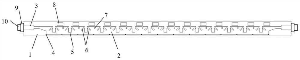
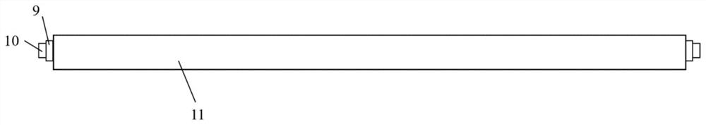
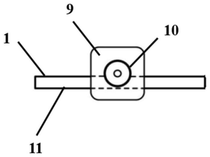
[0028] Such as figure 1 , figure 2 , image 3 The schematic diagram of the structure in each direction is shown, a microstrip leaky-wave antenna with stable gain periodically loaded with parasitic patches, including a dielectric plate 1, a metal transmission belt 2, a metal floor 11, a feed connector, an impedance matching part 7, and a parasitic patch sheet 8, the upper and lower layers of the dielectric board 1 are closely attached to the metal transmission belt 2 and the metal floor 11 respectively, the metal floor 11 and the metal transmission belt 2 are planar structures, the impedance matching part 7 is located on both sides of the metal transmission belt 2, and the feed connector Located on both sides of the dielectric board 1, the parasitic patch 8 is periodically loaded on the upper surface of the dielectric board 1, and it interacts with the metal transmission...


PUM


Abstract

The invention discloses a stable microstrip leaky-wave antenna capable of periodically loading a parasitic patch gain. The antenna comprises a dielectric plate, a metal conveying belt, a metal floor,a feed connector, an impedance matching part and parasitic patches, the upper layer and the lower layer of the dielectric plate are tightly attached to the metal transmission band and the metal floorrespectively, and the parasitic patches are periodically loaded on the upper surface of the dielectric plate; a plurality of groups of trifurcate grooves are periodically etched in the length direction of the metal conveying belt, and an additional small groove is formed between every two trifurcate grooves; metal nails and the trifurcate grooves are located on the two opposite sides of the metalconveying belt respectively, the additional small grooves and the trifurcate grooves are located on the same side of the metal conveying belt, and the parasitic patches are distributed on the side close to the trifurcate grooves in the metal conveying belt. According to the invention, the mutual compensation with the metal conveying belt by introducing a parasitic patch is overcome, and the radiation performance of the antenna is improved. In actual operation, the shape and the size of the parasitic patches and the position of the metal conveying belt can be adjusted according to different conditions, and the optimal radiation performance is achieved.

Description

technical field [0001] The invention relates to the field of wireless communication applications, in particular to a microstrip leaky-wave antenna with stable gain periodically loaded with parasitic patches. Background technique [0002] In recent years, science and technology have been continuously innovated and developed, and wireless communication technology has also produced a qualitative leap. It has been widely used in mobile communication, radar detection and other fields, and people's living standards have been significantly improved. In radio equipment, antennas are used to radiate and receive radio waves, and provide the required coupling between the transmitter or receiver and the medium that propagates radio waves, and play an important role in the field of wireless communications. With the innovation of communication technology and the advent of the 5G era, higher requirements are placed on the performance of antennas. Therefore, people in the related field hav...

Claims


Application Information

Patent Timeline
IPC IPC(8): H01Q13/20H01Q1/38
CPCH01Q13/206H01Q1/38
Inventor 张超群张明渝陈良兵周松
Owner NANCHANG UNIV
Why Eureka
Try Eureka