
Mushroom stem penetrating fermentation equipment

A technology for fermentation equipment and mushroom rods, which is applied to the field of mushroom rod penetration fermentation equipment, can solve problems such as insufficient penetration holes, influence on growth of mushrooms, slow penetration speed, etc., and achieve the effect of uniform distribution.

Active Publication Date: 2020-12-11
江西华香食品有限公司
View PDF7 Cites 1 Cited by
  • Summary
  • Abstract
  • Description
  • Claims
  • Application Information

AI Technical Summary

Problems solved by technology

[0003] People generally choose to punch holes in discarded tree trunks, so as to plant mushrooms on the punched trunks, but because there are not many discarded tree trunks, people generally fill bags with the nutrients needed for mushrooms. , and put the spores of the mushrooms in it, let it ferment, and make it into mushroom stems. After the fermentation is completed, punch holes in the mushroom stems so that the mushrooms can grow. People usually use manual methods Penetrate the mushroom stem, this kind of penetration makes the penetration speed slower, and the penetrated holes are not uniform enough, which may have a certain impact on the growth of the mushroom

Method used


Image

  • Mushroom stem penetrating fermentation equipment
  • Mushroom stem penetrating fermentation equipment
  • Mushroom stem penetrating fermentation equipment

Examples


Embodiment 1

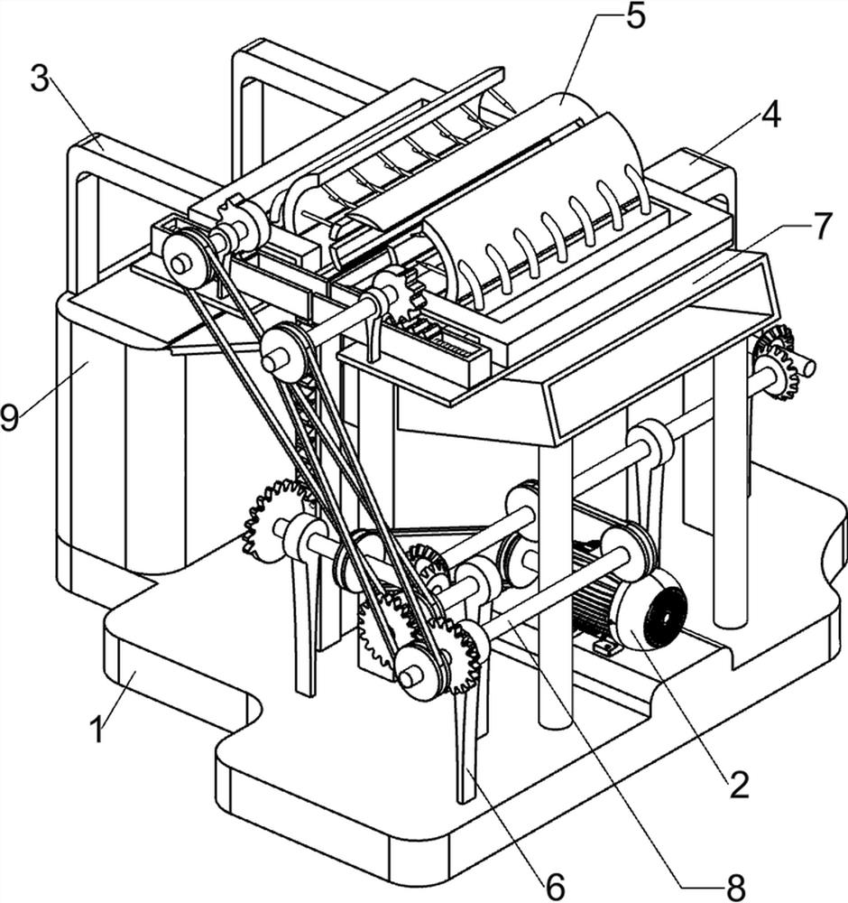
[0025] A kind of mushroom rod penetrating fermentation equipment, such as figure 1 As shown, it includes a base plate 1, a servo motor 2, a first L-shaped rod 3, a second L-shaped rod 4, a piercing mechanism 5, a first bearing seat 6, a loading and unloading mechanism 7 and a driving mechanism 8, and the upper right side of the base plate 1 A servo motor 2 is provided, a first L-shaped rod 3 is arranged symmetrically front and rear on the left side of the upper part of the bottom plate 1, a second L-shaped rod 4 is provided on the rear side of the upper part of the bottom plate 1, a loading and unloading mechanism 7 is arranged in the middle of the upper part of the bottom plate 1, and the bottom plate 1 Three first bearing blocks 6 are arranged on the right front side of the upper part, a piercing mechanism 5 is arranged on the upper part of the loading and unloading mechanism 7, and a driving mechanism 8 is arranged on the right side of the upper part of the bottom plate 1. ...

Embodiment 2

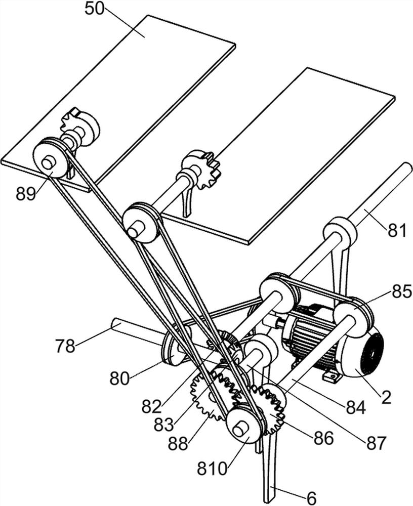
[0028] On the basis of Example 1, such as figure 2 , image 3 , Figure 4 and Figure 5 As shown, the piercing mechanism 5 includes a mounting plate 50, a second bearing seat 51, a second rotating shaft 52, a first slide rail 53, a first missing gear 54, a first rack 55, a first spring 56, and a second slide rail 57, slide block 58, puncture plate 59, curved connecting rod 510 and puncture tube 511, the first L-shaped bar 3 on both sides and loading and unloading mechanism 7 are all provided with mounting plate 50, and the mounting plate 50 tops of both sides are arranged A second bearing seat 51 is provided, and a second rotating shaft 52 is provided in the second bearing seat 51. The second rotating shaft 52 on both sides is provided with a first missing gear 54. A first slide rail 53 is provided, and a first rack 55 is slidably provided in the first slide rail 53, and the first rack 55 meshes with the first missing gear 54. Between the first slide rail 53 and the first ra...

Embodiment 3

[0035] On the basis of Example 2, such as figure 1 , Figure 6 and Figure 7 As shown, a blanking box 9 is also included, and the left side of the bottom plate 1 is provided with a blanking box 9.

[0036] When the baffle plate 712 moves downward and no longer blocks the mushroom rod, the mushroom rod that has been punctured will fall downwards in the lower material box 9, and when the mushroom rod in the lower material box 9 reaches a certain amount, the user can take it out The mushroom bar in the feeding box 9.

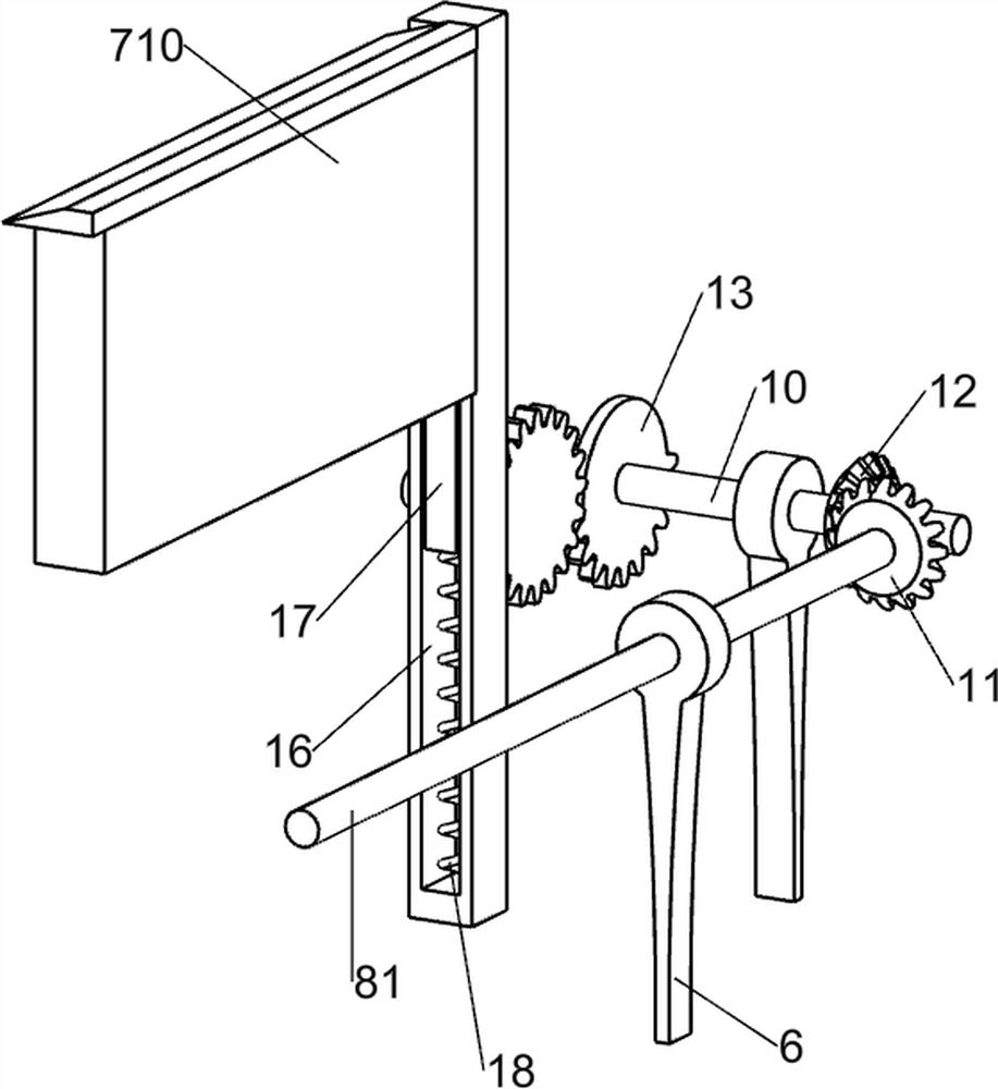
[0037] Also include the first rotating rod 10, the third bevel gear 11, the fourth bevel gear 12, the third missing gear 13, the second rotating rod 14, the third gear 15, the fourth slide rail 16, the third rack 17, The third spring 18 and the fourth bearing seat 19, two fourth bearing seats 19 are provided on the rear side of the bottom plate 1 top, and the fourth bearing seat 19 on the right side is provided with the first rotating rod 10 in a rotating manner...


PUM


Abstract

The invention relates to penetrating fermentation equipment, in particular to mushroom stem penetrating fermentation equipment. According to the mushroom stem penetrating fermentation equipment, mushroom stems can be rapidly penetrated, and penetrating holes are uniform and tidy. The mushroom stem penetrating fermentation equipment comprises a bottom plate, a servo motor, first L-shaped rods and asecond L-shaped rod, wherein the whole mushroom stem penetrating fermentation equipment is arranged on the bottom plate; the servo motor is arranged on one side of the upper part of the bottom plate;the first L-shaped rods are symmetrically arranged on the other side of the upper part of the bottom plate; and the second L-shaped rod is arranged on the upper part of the bottom plate. The effectsthat the mushroom stems can be rapidly penetrated, and the penetrating holes are uniform and tidy are achieved; after mushrooms are moved to the positions in puncture cylinders, the mushrooms are moved through puncture plates on the two sides, so that the mushroom stems can be rapidly punched, and due to the fact that thorns on the puncture plates are evenly distributed, the effect of even punching can be achieved.

Description

technical field [0001] The invention relates to penetrating fermentation equipment, in particular to mushroom stem penetrating fermentation equipment. Background technique [0002] Mushroom food is rich in protein, dietary fiber, carbohydrates, vitamins and trace elements. Dry products such as shiitake mushrooms and mushrooms have more protein content. In addition to providing rich nutrients, mushroom food also has health benefits. Studies have found that the polysaccharides contained in mushroom food have the effects of improving immunity, lowering blood fat, and anti-tumor. People's demand for mushrooms is increasing, so people begin to cultivate mushrooms in batches. [0003] People generally choose to punch holes in discarded tree trunks, so as to plant mushrooms on the punched trunks, but because there are not many discarded tree trunks, people generally fill bags with the nutrients needed for mushrooms. , and put the spores of the mushrooms in it, let it ferment, a...

Claims


Application Information

Patent Timeline
Patent Type & Authority Applications(China)
IPC IPC(8): A01G18/60
CPCA01G18/60Y02W30/40
Inventor 刘小红
Owner 江西华香食品有限公司
Learn More