Bottom member and heat loops

a bottom member and heat loop technology, applied in the field of underground heat exchange systems, can solve the problems of difficult for customers to predict the operating cost and financial payback associated with ground source installation, the cost of installing certain prior art vertical ground source heat loops can account for nearly half of the total cost incurred, and achieve the effect of facilitating system movemen

Inactive Publication Date: 2005-03-01
ENLINK GEOENERGY SERVICES
View PDF93 Cites 29 Cited by
  • Summary
  • Abstract
  • Description
  • Claims
  • Application Information

AI Technical Summary

Benefits of technology

In one system and method according to the present invention a coiled tubing unit (CTU) is used to drill heat loop bore holes. The CTU has a reel on which is wrapped continuous flexible steel tubing, an injector which transports the tubing into and out of the hole, a drill bit on the end of a down hole motor, and a pump which supplies fluid for drilling. The motor is rotated by the pump pressure from the surface, which allows the unit to drill without rotating the drill string. This feature results in several benefits not possible with conventional drilling rigs. Directional drilling allows multiple wells to be drilled from one location. It also reduces the space required between bore holes and allows them to be drilled in a very close proximity to the subject building. This process not only reduces 80 percent of trenching on some jobs, but allows the unit to drill under existing slabs, driveways, parking lots and buildings. The compact design and directional drilling capabilities opens the retrofit market to geothermal systems.
With a method according to the present invention a relatively short surface trench is excavated before drilling is started. The drilling machine straddles the trench, drilling bore holes in the bottom of the trench as it moves over the length of the trench. A solids control system which cleans the drilling fluid as it is pumped from the hole, allowing cuttings to be dry discharged in a designated area, thereby maintaining a clean, dry drill site. As each hole is drilled, a track mounted rig moves approximately two to three feet down the trench to the next drilling location. A grout reel is then positioned over the previously drilled hole. This reel has a flexible grout pipe wrapped around a powered reel. As the grout pipe is pushed down the bore hole, it takes a plastic heat loop with it to the bottom of the hole. In certain preferred embodiments the loop is secured in the hole with an anchor apparatus; then the grout pipe is retracted while filling the hole with grout. Since a sinker bar is not required in this process, a 3 to 3¾ inch diameter hole is drilled, in certain embodiments, compared to a conventional 4 to 4½ inch hole. This results in faster penetration, improved fuel efficiency, and improved heat transfer to the earth.
This invention provides these benefits: shorter surface trench and dry discharge results in less site damage; smaller bore hole increases system efficiency by improved heat transfer; total system installation time is reduced by at least 50 percent as compared to some prior art methods; and usable space is increased by drilling under slabs and other surface structures.
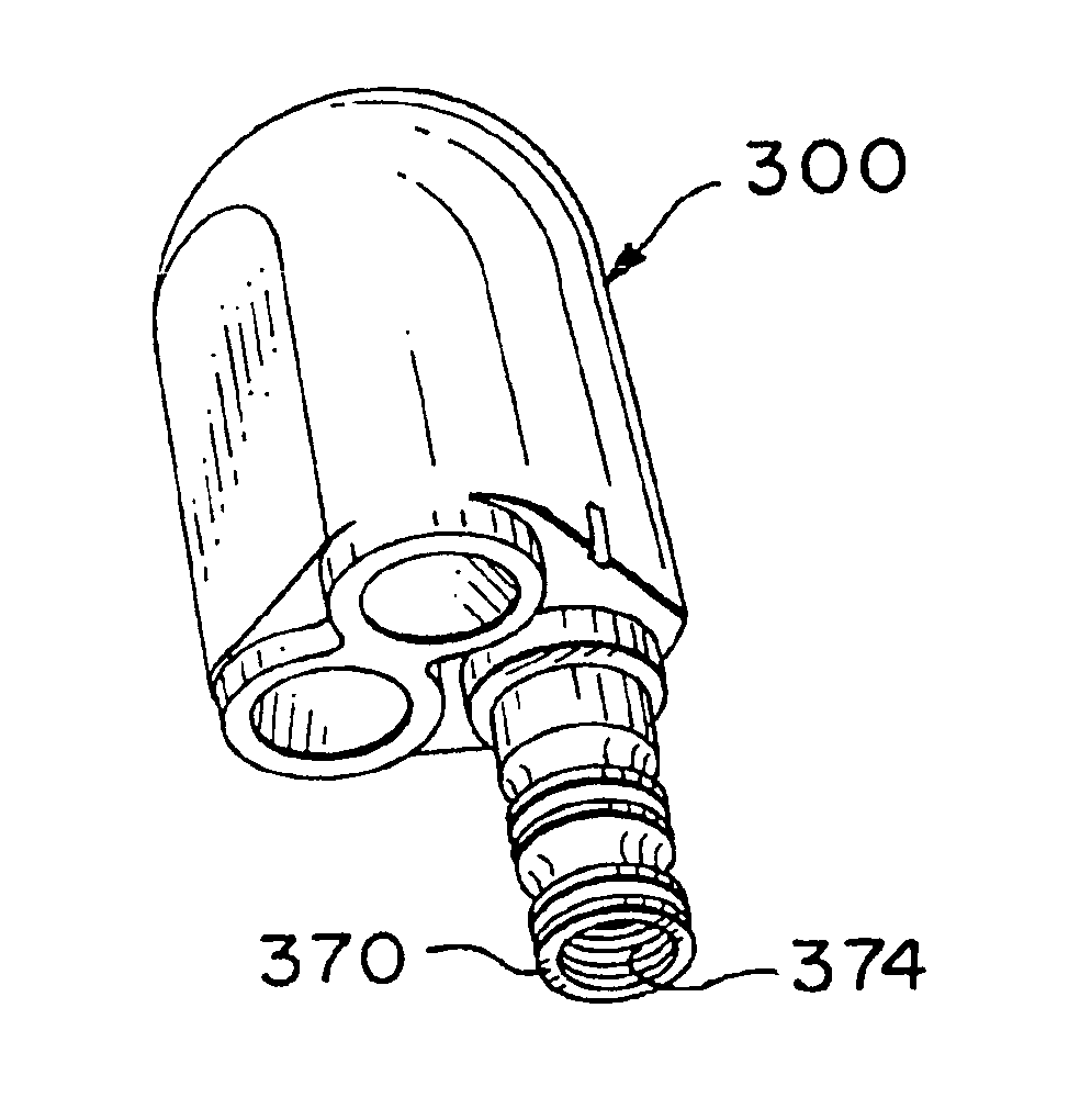
In certain embodiments, the present invention discloses a system with coil tubing and a grout pipe with a curved member or members or a solid or hollow ball or partial ball at the end of the pipes to facilitate movement of the system through a wellbore and to prevent the lower end of the system from hanging up on or being caught by a ledge or uneven portion of the wellbore.

Problems solved by technology

One reason ground source heat pumps have not been more widely used in the past is because of the expense involved in the design and installation of the circulating fluid pipe loop which must be buried in the ground.
The uncertainty of the installation costs coupled with the uncertainty of the resulting operating efficiencies have made it difficult for a customer to predict the operating costs and the financial payback associated with installing a ground source heat pump system.
The cost for the installation of certain prior art vertical ground source heat loops can account for nearly half of the total cost incurred in the installation of a geothermal heat pump system.
Several problems can arise in such methods: loop “insertion” difficulties caused by loop buoyancy; thermal conductivity and installation difficulties of borehole backfill materials; and environmental concerns.
Although the drilling of the hole may be relatively easy, certain problems may be encountered in inserting the loop.
This pipe material also has relatively poor stiffness.
Since the pipe has poor longitudinal stiffness, the pipe tends to bend or curl inside the well, creating additional frictional drag against the well wall until the pipe can be pushed no deeper.
Even when the pipe is filled with water, the loop still maintains considerable buoyancy because the drilled hole is filled with dense drilling mud.
However, the result is residual heavy drilling fluid in the well, creating a very dense slurry of clay, sand, rock, etc.—with resulting high buoyancy and low surface tension.
The considerable efforts made to overcome buoyancy of the loop caused by the density of the drill fluid are time consuming, expensive, and hazardous to the integrity of the loop.
Great expense and many tests and studies have been performed in a search for an optimum thermally conductive material that can be economically placed in the annular space between the loop pipe and the wellbore wall.
This insulating airspace results in “hot loops”, and the heat pump system either works poorly or not at all.
Although these grouts seem to work well in testing, there is great resistance from the field installers.
The mixture can be expensive to handle, difficult to mix, even more difficult to pump, and extremely rough on equipment because of the abrasion.
In addition, placing of the material in the borehole is difficult to control and monitor.
If grouting is attempted from the surface, “bridging” can occur resulting in a partially filled hole.
If grouting from the bottom of the hole, “channeling” can occur, again resulting in a partially grouted hole.
When the water subsides in the borehole, this leaves air spaces, thus insulating the loop and reducing the efficiency of the system.
An additional disadvantage is that the voids from channeling as well as the interstitial spacing between the individual sand (or other solid particles) create permeability.
Permeability that creates a vertical communication path by which the ground water system could be contaminated by surface spills is an environmental concern.
The prior art cementitious grouts, developed to overcome the permeability objection, have some unique problems of their own.
In addition to all of the handling, mixing, pumping, abrasion, and conductivity problems of the High Solids Thermally Conductive Grouts, the “heat of hydration” generated when cement cures, causes grout to “shrink” away from the polyethylene pipe.
Although the permeability of the cured grout itself is very low, a flow path may now exist between the polyethylene pipe and the grout—again insulating the loop and threatening the environment.
Because of its inherent structure, polyethylene is a very high molecular weight wax or paraffin, and does not bond well with anything, even under laboratory controlled conditions.
Attempts to control grout shrinkage and cement to polyethylene bonding in the field were proven unsuccessful.
The trenching and manifolding of the surface pipe typically takes as much time as the wellbore drilling and pipe installation.

Method used


Image

  • Bottom member and heat loops
  • Bottom member and heat loops
  • Bottom member and heat loops

Examples


Embodiment Construction

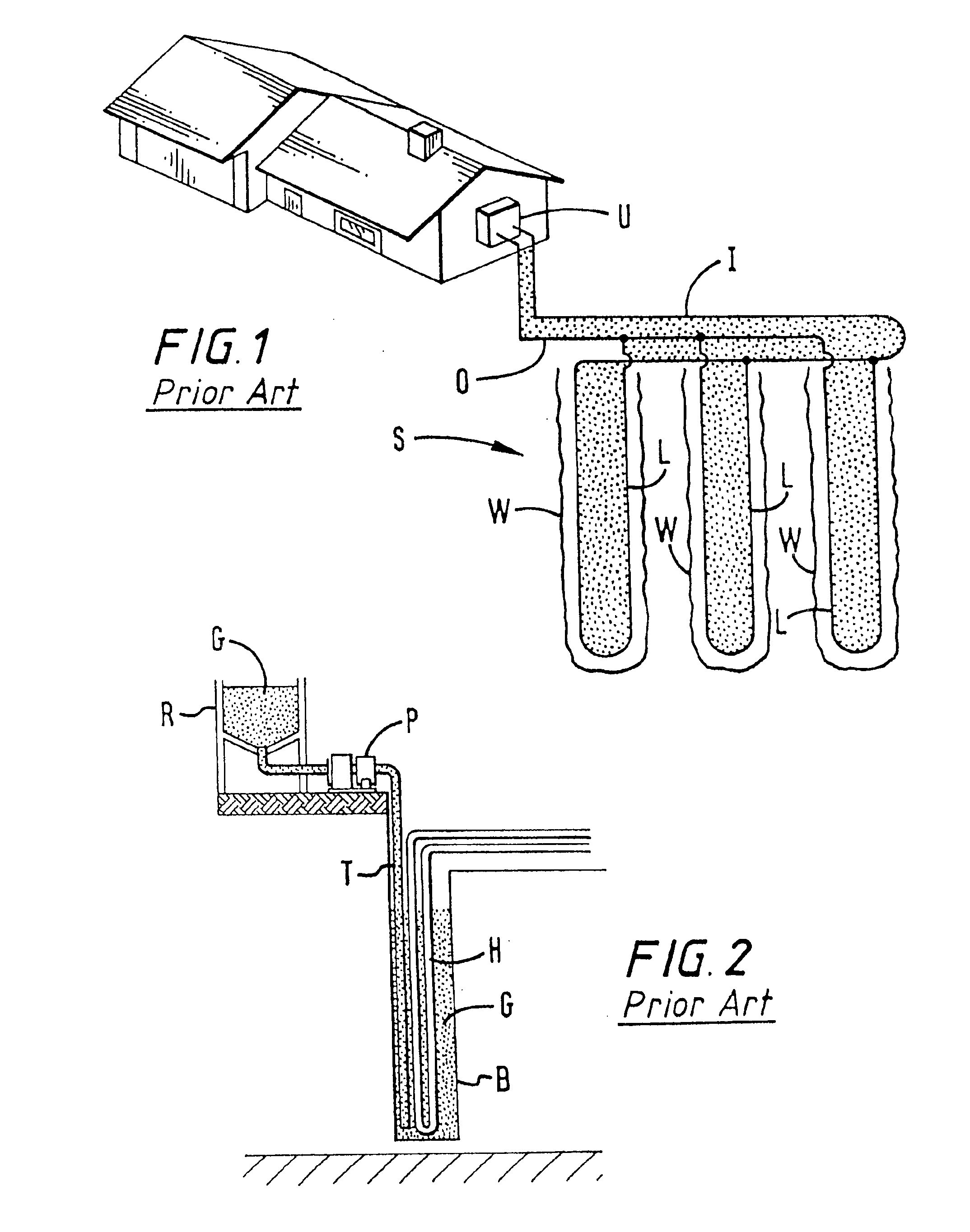
Referring now to FIG. 1, a prior art underground heat exchange pipe loop system S has a plurality of wellbores W, each e.g. about 250 feet deep and 4 to 4.5 inches in diameter, which are preferably, between about ten feet to fifteen feet apart. Water flows from a building's processing unit U in an inlet pipe I into each inlet side of a plurality of pipe heat exchange loops L and then flows up in each outlet side of the loops L to an outlet pipe O which is in fluid communication with the processing unit U. Pipes I and O are typically about 45 feet long for a three loop system as shown (preferably about ten to fifteen feet between each loop).

FIG. 2 illustrates a prior art system and method for grouting a wellbore such as the wellbores W in FIG. 1. After a pipe heat exchange loop H is installed in a wellbore B, a grout pipe T is inserted into the wellbore B. A grout pump P then pumps grout G from a reservoir R down the grout pipe T from which it flows into the wellbore B.

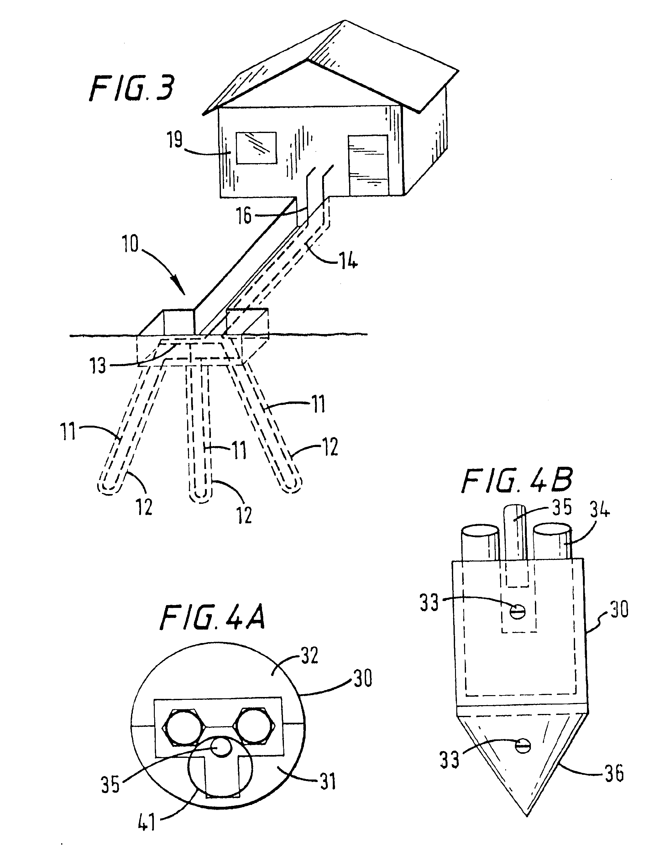
FIG. 3 shows a...


PUM

PropertyMeasurementUnit
specific gravityaaaaaaaaaa
depthaaaaaaaaaa
diameteraaaaaaaaaa

Abstract

Bottom members for a heat loop for an earth energy transfer system with a moving energy transfer fluid and heat loops with such a bottom member; the bottom member in one aspect including a body with a top surface and a bottom surface, the body configured for connection at a lower end of the heat loop, the bottom surface shaped to facilitate passage of the heat loop through a borehole extending down into the earth.

Description

BACKGROUND OF THE INVENTION1. Field of the InventionThe present invention is directed to underground heat exchange systems; to apparatus and methods for installing a loop of pipe in a hole in the earth; and to thermally conductive filler materials for emplacement between the pipe loop and the interior hole wall.2. Description of Related ArtThe outstanding efficiency of closed loop ground source heat pumps is well known. In a typical system, for each unit of energy purchased from an electric utility to operate the system, 4 units of energy are extracted from or put into the earth in the form of heat. In order to exchange this heat with the earth, a closed loop pipe or series of closed loop pipes are buried in the ground. A heat exchange fluid is circulated through this buried pipe system. If a difference exists between the temperature of the fluid circulating in the pipe and the earth temperature, an exchange of heat occurs—primarily by conduction through the wall of the pipe. If the...

Claims


Application Information

Patent Timeline
Patent Type & Authority Patents(United States)
IPC IPC(8): E21B23/00E21B33/13F28F27/00F25B30/06F25B30/00F28D20/00
CPCE21B23/00E21B33/13F24J3/083F28D20/0052F28F27/00F25B30/06F24J2003/088F24J2003/089Y02E60/142F28F21/062Y02E10/125F24T2010/53F24T2010/56F24T10/15Y02E10/10Y02E60/14
Inventor JOHNSON, JR., HOWARD E.AMERMAN, THOMAS R.
Owner ENLINK GEOENERGY SERVICES
Why Eureka
Try Eureka