
Laser welding flue gas treatment and purification device and purification method thereof

A flue gas treatment and purification device technology, which is applied in the direction of chemical instruments and methods, separation methods, combined devices, etc., can solve problems such as rising ambient temperature, failure to achieve expected results, incomplete absorption, etc., to improve the sense of use and reduce Manual operation is troublesome and the effect of reducing energy waste

Active Publication Date: 2022-04-05
长春市云顶智能装备有限公司
View PDF0 Cites 0 Cited by
  • Summary
  • Abstract
  • Description
  • Claims
  • Application Information

AI Technical Summary

Problems solved by technology

[0004] The purpose of the present invention is: in order to solve the problem that the existing laser welding fume treatment and purification device adopts a group of suction heads to absorb the fume during the process of absorbing the fume. The small diameter of the suction head will lead to incomplete absorption, and the large diameter of the suction head will not only cause Energy consumption is wasted, and it is not targeted. The flue gas absorbed by the existing laser welding flue gas treatment and purification device carries heat energy, and directly purifying and discharging it will cause waste of heat energy and increase the ambient temperature. The existing laser welding flue gas Treatment and purification devices often use activated carbon and filters to block and adsorb particles in the flue gas. The filters and activated carbon inside the device need to be replaced frequently, otherwise the expected effect will not be achieved, but frequent manual replacement will cause troublesome operations. Provide laser welding fume treatment and purification device and its purification method

Method used


Image

  • Laser welding flue gas treatment and purification device and purification method thereof
  • Laser welding flue gas treatment and purification device and purification method thereof
  • Laser welding flue gas treatment and purification device and purification method thereof

Examples


Embodiment Construction

[0030] The following will clearly and completely describe the technical solutions in the embodiments of the present invention with reference to the accompanying drawings in the embodiments of the present invention. Obviously, the described embodiments are only some, not all, embodiments of the present invention. Based on the embodiments of the present invention, all other embodiments obtained by persons of ordinary skill in the art without making creative efforts belong to the protection scope of the present invention.

[0031] In the description of the present invention, it should be noted that the terms "center", "upper", "lower", "left", "right", "vertical", "horizontal", "inner", "outer" etc. The indicated orientation or positional relationship is based on the orientation or positional relationship shown in the drawings, and is only for the convenience of describing the present invention and simplifying the description, rather than indicating or implying that the referred d...


PUM


Abstract

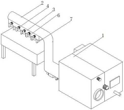
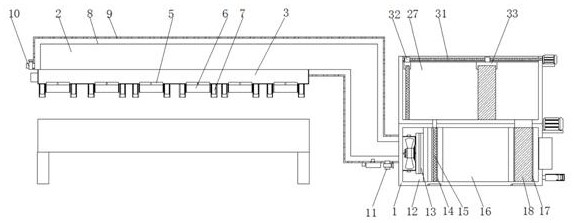
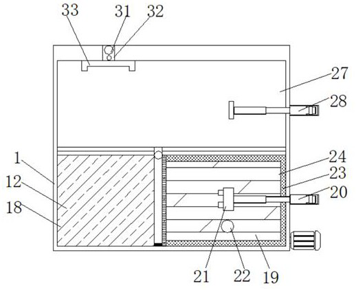
The invention discloses a laser welding flue gas treatment and purification device and a purification method thereof, and relates to the field of laser welding, including an installation bin, one end of the installation bin is connected with a dust suction pipe, and a connecting block is arranged under the dust suction pipe, the A motor is installed on the outside of the connection block, and a rotating plate is connected to the inside of the connection block, and a smoke inlet is connected to the bottom end of the connection block. The present invention realizes that multiple groups of smoke inlets are set above the workpieces to be welded through the installation bin, vacuum pipe, connection block, motor, rotating plate, smoke inlet, and photosensitive sensor, but the dust suction of the smoke inlet Not all channels are open. Only when the photosensitive sensor senses that the corresponding area is being welded, the corresponding channel will be opened, thus making the vacuuming more targeted. In the case of a certain energy consumption, closing other channels will make the welding area The dust suction effect is better, and the dust suction channel moves with the welding area, and the welding area is not restrictive.

Description

technical field [0001] The invention relates to the field of laser welding, in particular to a laser welding fume treatment and purification device and a purification method thereof. Background technique [0002] Laser welding is an efficient and precise welding method that uses a high-energy-density laser beam as a heat source. Laser welding is one of the important aspects of the application of laser material processing technology. In the 1970s, it was mainly used for welding thin-walled materials and low-speed welding. The welding process is of heat conduction type, that is, the laser radiation heats the surface of the workpiece, and the surface heat diffuses to the inside through heat conduction. By controlling parameters such as laser pulse width, energy, peak power and repetition frequency, the workpiece is melted to form a specific molten pool. Due to its unique advantages, it has been successfully applied in the precision welding of micro and small parts. [0003] Th...

Claims


Application Information

Patent Timeline
Patent Type & Authority Patents(China)
IPC IPC(8): B03C3/017B01D50/00B08B15/04
CPCB01D50/00B08B15/04
Inventor 吴彩伍
Owner 长春市云顶智能装备有限公司
Learn More