Chain link positioning and machining clamp device

A fixture device and chain link technology, which is applied in the direction of workpiece clamping devices and manufacturing tools, can solve the problems of low processing strength of positioning processing fixtures, inability to position and fix chain links, and poor positioning accuracy, so as to avoid measurement operations, The effect of saving steps and facilitating processing

Pending Publication Date: 2020-12-11
江苏宏大特种钢机械厂有限公司
View PDF0 Cites 0 Cited by
  • Summary
  • Abstract
  • Description
  • Claims
  • Application Information

AI Technical Summary

Problems solved by technology

[0004] Aiming at the deficiencies of the prior art, the present invention provides a chain link positioning and processing fixture device, which ensures that the chain link can perform a preliminary positioning function before clamping and fixing, avoids the need for measurement work before positioning, saves procedures, and facilitates subsequent positioning processing , improve the processing accuracy of the workpiece, improve the qualified rate of the product, make the support degree of the positioning and clamping effect better, and will not make the positioning support force shift, etc., and solve the current chain link clamping method. The two round holes are clamped separately, and the positioning accuracy is poor. It needs to be measured before positioning to complete the positioning. The process is cumbersome, and it is easy to loosen during processing, which is not conducive to processing. At the same time, the accuracy is highly dependent on the technical level of the workers and the accuracy of the measuring tools. , will produce large errors, which will increase the unqualified rate of processing, and the processing strength of the current positioning processing fixture is low, and the chain link cannot be stably positioned, clamped and fixed.

Method used


Image

  • Chain link positioning and machining clamp device
  • Chain link positioning and machining clamp device
  • Chain link positioning and machining clamp device

Examples


Embodiment Construction

[0025] The following will clearly and completely describe the technical solutions in the embodiments of the present invention with reference to the accompanying drawings in the embodiments of the present invention. Obviously, the described embodiments are only some, not all, embodiments of the present invention. Based on the embodiments of the present invention, all other embodiments obtained by persons of ordinary skill in the art without making creative efforts belong to the protection scope of the present invention.

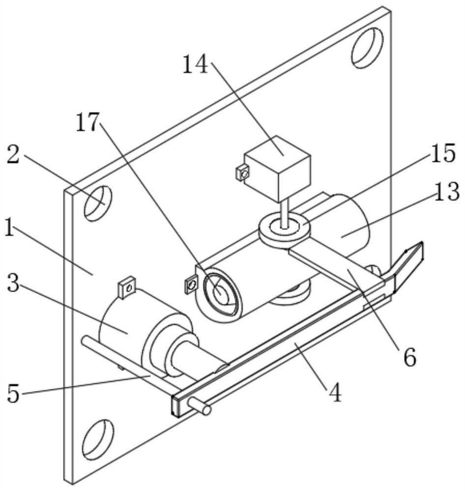
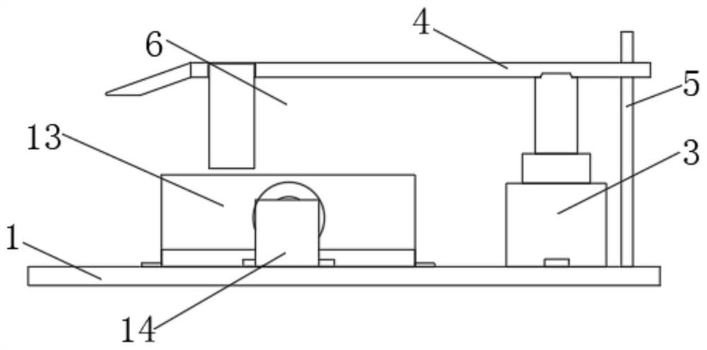
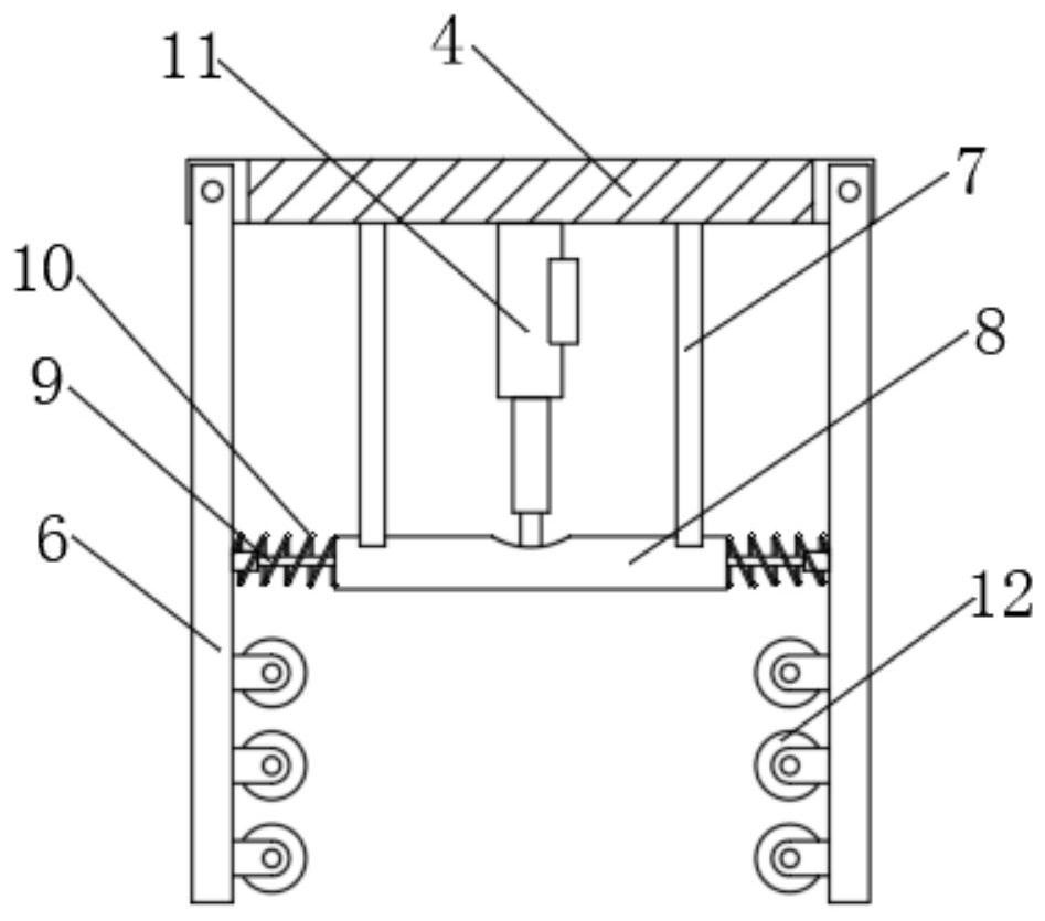
[0026] see Figure 1-6 , a chain link positioning and processing fixture device, comprising a positioning plate 1, threaded holes 2 are provided at the four corners of the front end of the positioning plate 1, a hydraulic cylinder 3 is fixedly installed on one side of the top end of the positioning plate 1, and the output end of the hydraulic cylinder 3 is fixed. Connected with a pressure transmission rod 4, the side wall of the pressure transmission rod 4 is ...


PUM


Abstract

The invention relates to the technical field of machining, and discloses a chain link positioning and machining clamp device. The chain link positioning and machining clamp device comprises a positioning plate, threaded holes are formed in four corners of the front end of the positioning plate, a hydraulic cylinder is fixedly installed on one side of the top end of the positioning plate, the output end of the hydraulic cylinder is fixedly connected with a pressure transmission rod, a positioning clamping mechanism is arranged on the side wall of the pressure transmission rod, a sleeve and a driving motor are arranged at the top end of the positioning plate, a bearing locking plate is fixedly connected to the output end of the driving motor, a gear is fixedly connected to one end of the bearing locking plate through a connecting shaft, supporting heads are slidably connected to the two ends in the sleeve correspondingly, and a plurality of racks are correspondingly and fixedly connectedto one side of the supporting heads. According to the chain link positioning and machining clamp device, it is guaranteed that a chain link can be preliminarily positioned before being clamped and fixed, the situation that measurement operation is needed before positioning is avoided, procedures are reduced, and the positioning and supporting acting force cannot deviate.

Description

technical field [0001] The invention relates to the technical field of mechanical processing, in particular to a chain link positioning processing jig device. Background technique [0002] The chain link is an important component of some large-scale mechanical engineering equipment such as a chain grate. It usually consists of two symmetrical chain pieces (that is, a pair of chain pieces form a chain link). Therefore, for two pieces in the same section The structural symmetry of the chain piece requires high precision. The chain piece body is usually a forged steel piece. There are two coaxial round holes on the chain piece body. The outer side of the chain piece is usually the preliminary forming surface during forging. Because it is a mechanical equipment Therefore, the assembly accuracy requirements of the chain links are very strict, especially the structural symmetry accuracy requirements of the two chain pieces in the same section and the assembly accuracy between the ...

Claims


Application Information

Patent Timeline
Patent Type & Authority Applications(China)
IPC IPC(8): B25B11/00
CPCB25B11/00
Inventor 朱强龙秦伟康
Owner 江苏宏大特种钢机械厂有限公司
Why Eureka
Try Eureka