A main building structure with an auxiliary equipment installation bracket

A technology for installing brackets and building main bodies, which is applied to building components, building structures, buildings, etc., can solve the problems of lack of external equipment fixing needs, damage to the overall stress of prefabricated parts, and reduced seismic strength of prefabricated parts, so as to facilitate subsequent maintenance. , Improve installation adaptability, improve installation adaptability

Active Publication Date: 2021-12-07
淮北淮海建设工程有限责任公司
View PDF6 Cites 0 Cited by
  • Summary
  • Abstract
  • Description
  • Claims
  • Application Information

AI Technical Summary

Problems solved by technology

[0003] Chinese patent document CN208363650U discloses a mounting bracket for a prefabricated component and a prefabricated wall containing the bracket. One of the mounting brackets for a prefabricated component includes an upper support plate and a lower support plate oppositely arranged. The upper end of the lower support plate is fixed to the lower adjustment column opposite to the upper adjustment column. The upper adjustment column is provided with a positive thread, and the lower adjustment column is provided with a reverse thread. The height of the mounting bracket of the prefabricated component prepared by this method can be adjusted with prefabricated floors of different thicknesses, and the application range is wider, but the mounting bracket of the prefabricated component can only be adjusted for the prefabricated floor, and lacks the need for fixing external equipment Opening the hole, opening the hole again will destroy the overall stress of the prefabricated part, resulting in a decrease in the seismic strength of the prefabricated part, and the slotting can only be adapted to the current equipment, which will affect the replacement and adaptation of subsequent equipment

Method used


Image

  • A main building structure with an auxiliary equipment installation bracket
  • A main building structure with an auxiliary equipment installation bracket
  • A main building structure with an auxiliary equipment installation bracket

Examples


Embodiment approach

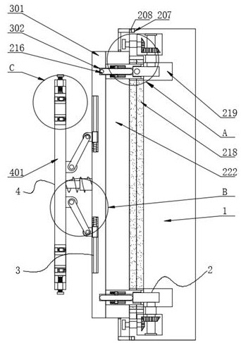
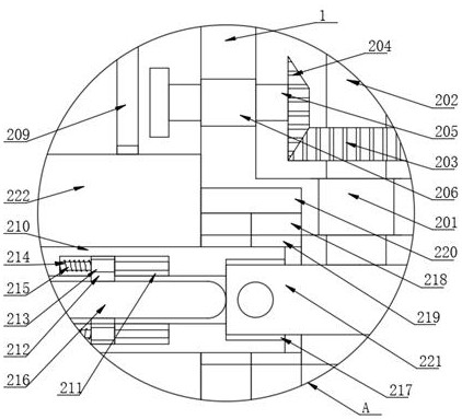
[0046] The specific implementation method is: after the wall body 1 is assembled, the shock absorbing plate 222 is moved into the through hole 219 on one side of the wall body 1, and the second rotating shaft 205 is driven in the second bearing 206 by forwardly turning the handle. Rotate, the protective shell 209 outside the handle can enter the first chute 207 through the first slider 208 on one side, so as to ensure the protective support of the protective shell 209 to the handle, and facilitate pulling and disassembly. The second rotating shaft 205 rotates to drive the driving gear 204 to rotate , the driving gear 204 rotates to drive the driven gear 203 and the first rotating shaft 202 to rotate, and the first rotating shaft 202 rotates to drive the bottom clamping plate 221 to move into the card slot 217 on one side of the card holder 210, and the protrusion on the side of the clamping plate 221 and the clamping groove 217 The inner cavity is pressed and fixed, so that the...


PUM


Abstract

The invention discloses a main body structure of a building with an auxiliary equipment installation bracket, which belongs to the field of prefabricated buildings, and includes a wall body. Both sides of the wall body are provided with clamping mechanisms, and the wall body is connected by clamping The mechanism is clamped with a shock absorbing mechanism, and a mounting mechanism is provided on one side of the shock absorbing mechanism. The clamping mechanism includes a first rotating shaft, and two first bearings are sleeved on the outer wall of the first rotating shaft. The main structure of the building with the auxiliary equipment installation bracket disclosed by the present invention can be disassembled by moving the card board out of the card slot as a shock absorber and a shock absorber plate, and the mounting seat in the inner cavity of the bracket can facilitate the staff to install the auxiliary equipment Fixed, no additional assembly slots are required to improve the installation adaptability, thus effectively improving the assembly efficiency of the shock absorber and one side bracket, effectively facilitating subsequent maintenance, and significantly increasing the installation and fixing requirements for auxiliary equipment.

Description

technical field [0001] The invention relates to the field of prefabricated buildings, more specifically, to a building main structure with auxiliary equipment installation brackets. Background technique [0002] The main body of the building refers to the structural structure of the building entity, including roofs, floors, beams, columns, supports, walls, joints and foundations, etc. The main body of the traditional building frame is mostly cast by reinforced concrete. The prefabricated building in which the main body of the building is assembled, its portable assembly can effectively shorten the building construction time. [0003] Chinese patent document CN208363650U discloses a mounting bracket for a prefabricated component and a prefabricated wall containing the bracket. One of the mounting brackets for a prefabricated component includes an upper support plate and a lower support plate oppositely arranged. The upper end of the lower support plate is fixed to the lower ...

Claims


Application Information

Patent Timeline
Patent Type & Authority Patents(China)
IPC IPC(8): E04B2/00E04G21/16E04B1/98E04H9/02E04B1/86
CPCE04B1/86E04B1/98E04B2/00E04G21/16E04H9/02
Inventor 王平王忠吴海龙
Owner 淮北淮海建设工程有限责任公司
Why Eureka
Try Eureka