Device for transforming compressed air pipeline in ship industry and transforming method

A compressed air pipeline, compressed air technology, applied in valve heating/cooling device, valve device, pipeline protection and other directions, can solve the problems of complex structure of compressed air water removal device, poor removal of moisture and impurities, etc. The effect of high water removal efficiency, improved maintainability, and enhanced efficiency

Pending Publication Date: 2020-12-11
江阴市大江环保科技有限公司
View PDF11 Cites 0 Cited by
  • Summary
  • Abstract
  • Description
  • Claims
  • Application Information

AI Technical Summary

Problems solved by technology

[0004] The structure of the compressed air water removal device used in the prior art is relatively complex, which is greatly affected by the change of ambient temperature, and the removal effect of water and impurities is not good

Method used


Image

  • Device for transforming compressed air pipeline in ship industry and transforming method
  • Device for transforming compressed air pipeline in ship industry and transforming method
  • Device for transforming compressed air pipeline in ship industry and transforming method

Examples


Embodiment 1

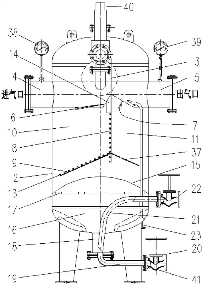
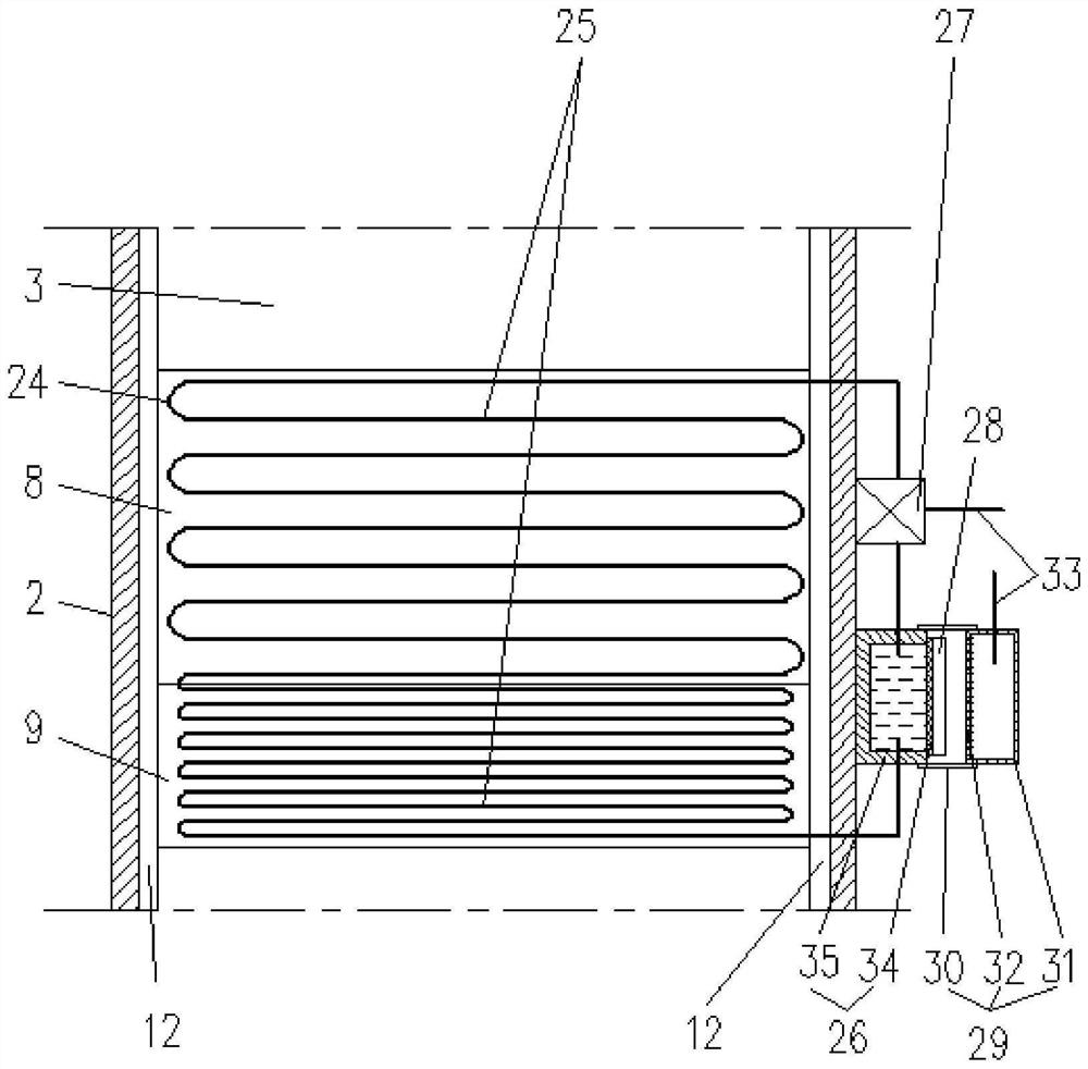
[0041] Such as Figures 1 to 6 Shown is an embodiment of a device for the transformation of compressed air pipelines in the shipbuilding industry, including a compressed air automatic separation device 1 for water accumulation and sedimentation. The partition plate 3 in the tank body 2, the air inlet pipe 4 and the air outlet pipe 5 inserted into the tank body 2 and separated on both sides of the partition plate 3, the air inlet pipe 4 is inserted into the tank body 2 is connected to one side of the partition plate 3, and one end of the outlet pipe 5 inserted into the tank body 2 is connected to the other side of the partition plate 3, and the inlet pipe 4 The lower part of the connection between the upper part and the partition plate 3 is provided with a first oblique cutout 6, and compressed air is formed between the first oblique cutout 6 and the partition board 3 and enters the tank body 2 from the air intake pipe 4. In the gas inlet port, a second oblique slit 7 is provi...

Embodiment 2

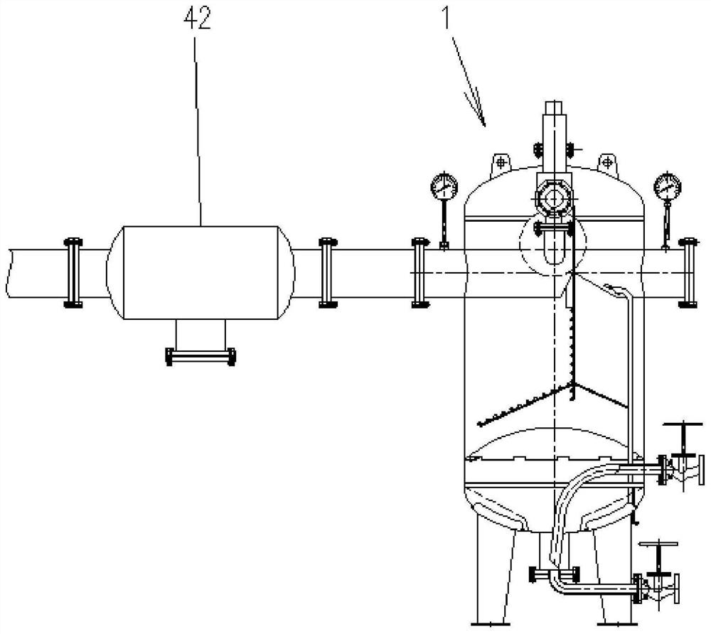
[0054] A compressed air pipeline transformation method using the device for the transformation of compressed air pipelines in the shipbuilding industry according to Embodiment 1 includes installing a compressed air water accumulation and sedimentation automatic separation device 1 in series on the pipeline of the compressed air terminal.

[0055] Preferably, a decontamination device 42 can also be installed in series on the pipeline of the compressed air terminal.


PUM


Abstract

The invention discloses a device for transforming a compressed air pipeline in the ship industry. The device comprises a water gathering and dirt settling automatic separation device consisting of a tank body, a partition plate, an air inlet pipe, an air outlet pipe and the like, one end of the air inlet pipe is connected with one surface of the partition plate, and one end of the air outlet pipeis connected to the other surface of the partition plate. A first oblique notch is formed in the lower portion of a connecting position of the air inlet pipe and the partition plate and an air guide-in opening allowing compressed air to enter the tank body from the air inlet pipe is formed, and a second oblique notch is formed in the lower portion of a connecting position of the air outlet pipe and the partition plate and an air guide-out opening allowing the compressed air to be output into the air outlet pipe from the tank body is formed. The lower end of the partition plate is sequentiallyconnected with an impact plate and a flow guiding plate, the partition plate, the impact plate and the flow guiding plate are sequentially connected and then divide an inner cavity in the upper portion of the tank body into an air inlet chamber and an air outlet chamber, convex ribs are arranged on the faces, facing the air inlet chamber, of the impact plate and the flow guiding plate, and a waterblocking and air guiding groove is formed in the air guide-in opening. The device is good in maintainability and high in water removal efficiency.

Description

technical field [0001] The invention relates to the technical field of compressed air pipeline equipment, in particular to a device and a reconstruction method for the reconstruction of compressed air pipelines in the shipbuilding industry. Background technique [0002] Compressed air supply system is one of the important energy sources in ship repair yards, shipyards and marine equipment industries. It is mainly used for sandblasting and painting, special coating, plasma cutting, pneumatic hoist, pneumatic tools, etc. As we all know, the atmosphere contains other corrosive gases, water vapor, hydrocarbons and solid particles. After these moisture and impurities are sucked by the compressor, they enter the compressed air pipe network system together with compressed air, residual oil, water vapor, etc. Corrosion of roads has caused considerable problems for industrial enterprises. Whether the main indicators such as the pressure, flow rate and water content of compressed air...

Claims


Application Information

Patent Timeline
Patent Type & Authority Applications(China)
IPC IPC(8): F17D3/14F16L59/16F16T1/00F16K49/00B01D53/26
CPCF17D3/145F16L59/168F16T1/00F16K49/002B01D53/26B01D53/265
Inventor 吕江吕德义
Owner 江阴市大江环保科技有限公司
Why Eureka
Try Eureka