
Numerical simulation method and system for solid propellant waste cutting treatment

A solid propellant and numerical simulation technology, which is applied in the fields of electrical digital data processing, design optimization/simulation, CAD numerical modeling, etc., can solve problems such as long cycle time, affecting the objectivity of results, and failure to obtain dynamic details

Active Publication Date: 2020-12-11
NORTHWESTERN POLYTECHNICAL UNIV
View PDF5 Cites 0 Cited by
  • Summary
  • Abstract
  • Description
  • Claims
  • Application Information

AI Technical Summary

Problems solved by technology

The main disadvantages of this method are: (1) a special site is required to carry out the experiment; (2) a large amount of manpower, material and financial resources are required; (3) the cycle of the experiment is long, and failures often occur, and repeated experiments are required. Further increase the cost; (4) Many uncertain factors in the test process cannot be controlled, so sometimes the experimental results obtained are different from the real process
The main disadvantages of this method are: (1) The analysis of the mechanism depends on the results of the experiment, and the phenomena that cannot be captured by the experiment will have blind spots in the process of mechanism analysis, which will affect the accuracy of the theoretical model; The model usually contains many artificial parameters, and the accuracy of the prediction results is closely related to these artificial parameters, which affects the objectivity of the results; (3) only the final results and conclusions can be obtained through the theoretical model, and the details of the dynamic process cannot be obtained. Dynamically capture typical phenomena in the cutting process, and there are often large differences between the estimated results and the actual results

Method used


Image

  • Numerical simulation method and system for solid propellant waste cutting treatment
  • Numerical simulation method and system for solid propellant waste cutting treatment
  • Numerical simulation method and system for solid propellant waste cutting treatment

Examples


Embodiment Construction

[0076] The following will clearly and completely describe the technical solutions in the embodiments of the present invention with reference to the accompanying drawings in the embodiments of the present invention. Obviously, the described embodiments are only some, not all, embodiments of the present invention. Based on the embodiments of the present invention, all other embodiments obtained by persons of ordinary skill in the art without making creative efforts belong to the protection scope of the present invention.

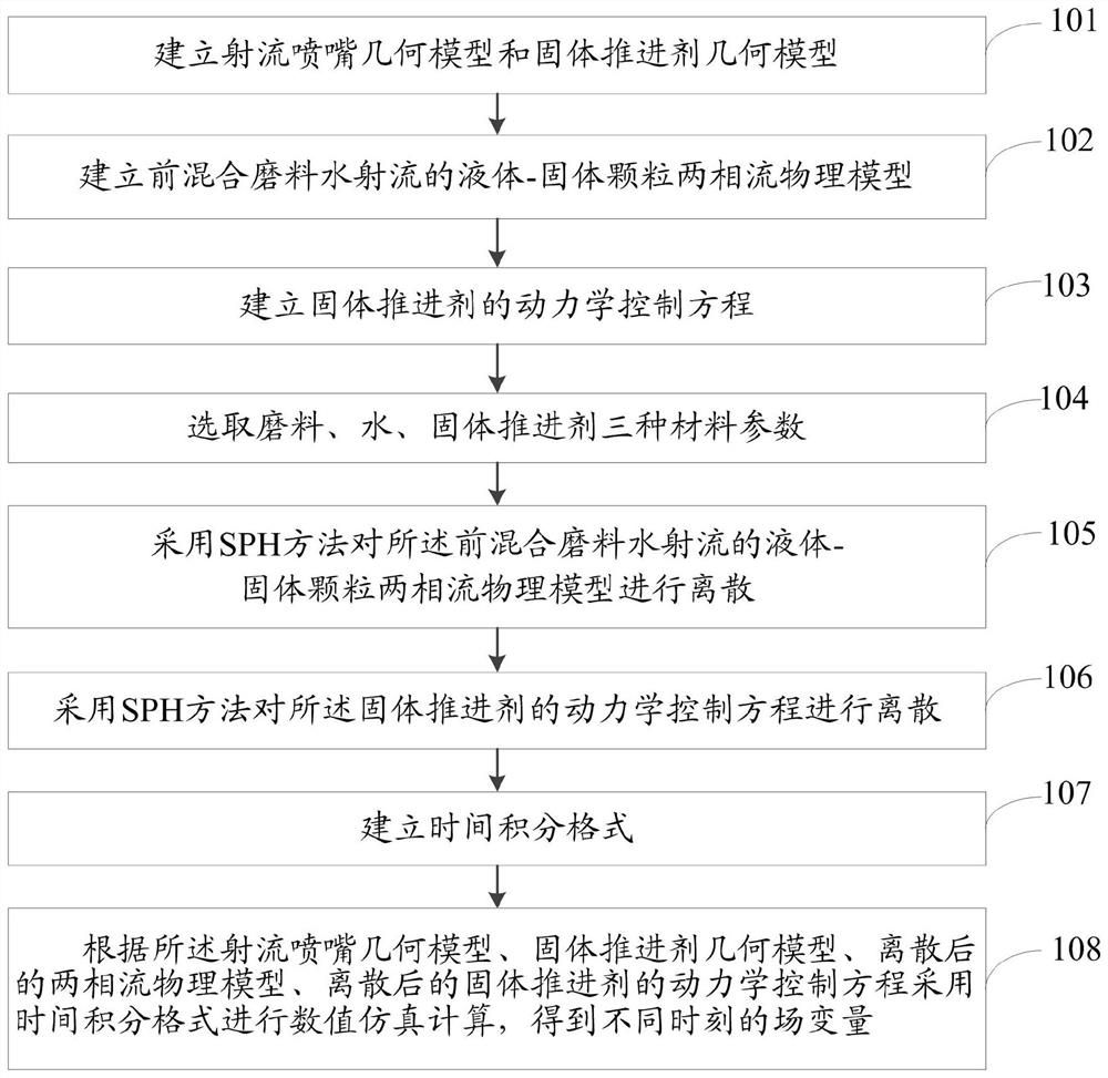
[0077] The purpose of the present invention is to provide a numerical simulation method and system for solid propellant waste cutting treatment, which can quickly and accurately determine field variables.

[0078] In order to make the above objects, features and advantages of the present invention more comprehensible, the present invention will be further described in detail below in conjunction with the accompanying drawings and specific embodiments.

[0079]...


PUM

PropertyMeasurementUnit
Densityaaaaaaaaaa
Densityaaaaaaaaaa
Particle sizeaaaaaaaaaa

Abstract

The invention relates to a numerical simulation method and system for solid propellant waste cutting treatment. The method comprises the steps of establishing a jet flow nozzle geometric model and a solid propellant geometric model; establishing a liquid-solid particle two-phase flow physical model of the pre-mixed abrasive water jet; establishing a kinetic control equation of the solid propellant; selecting three material parameters of an abrasive, water and the solid propellant; dispersing the liquid-solid particle two-phase flow physical model of the pre-mixed abrasive water jet by adoptingan SPH method; discretizing the kinetic control equation of the solid propellant by adopting the SPH method; establishing a time integral format; according to the jet flow nozzle geometric model, thesolid propellant geometric model, the discretized two-phase flow physical model and the discretized solid propellant dynamics control equation, carrying out numerical simulation calculation in a timeintegral format, so as to obtain field variables at different moments. According to the invention, the field variables can be quickly and accurately determined.

Description

technical field [0001] The invention relates to the technical field of cutting and processing solid propellant waste, in particular to a numerical simulation method and system for cutting and processing solid propellant waste. Background technique [0002] In military technical operations, the "disposal" of solid rocket motors is a task with great difficulty, high technical content and low safety factor. How to effectively remove the solid propellant in the engine, while ensuring a certain safety factor, and realize the effective recycling of the engine casing is one of the difficult problems to be solved by scientific research and technical personnel. The traditional or cutting method with a knife requires manual close-range work. Not only does the propellant drug harm the body, but the propellant is also prone to accidents such as combustion and explosion after being subjected to mechanical action; or the high-pressure water jet is used for cutting, although The cutting t...

Claims


Application Information

Patent Timeline
IPC IPC(8): G06F30/28G06F113/08G06F119/14G06F111/10
CPCG06F30/28G06F2113/08G06F2119/14G06F2111/10
Inventor 陈福振严红
Owner NORTHWESTERN POLYTECHNICAL UNIV
Learn More