Novel broadband high-balance-degree balun

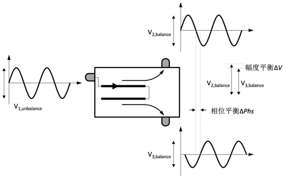
A new type of balanced technology, applied in impedance networks, electrical components, multi-terminal-pair networks, etc., can solve problems such as balun phase and amplitude imbalance, and achieve the effect of improving phase balance and amplitude balance.

Pending Publication Date: 2020-12-11
成都芯川电子有限公司
View PDF0 Cites 2 Cited by
  • Summary
  • Abstract
  • Description
  • Claims
  • Application Information

AI Technical Summary

Problems solved by technology

[0004] The technical problem to be solved by the present invention is that there is a certain phase and amplitude imbalance in the existing balun in the working state

Method used


Image

  • Novel broadband high-balance-degree balun
  • Novel broadband high-balance-degree balun
  • Novel broadband high-balance-degree balun

Examples


Embodiment 1

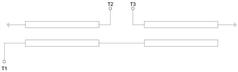
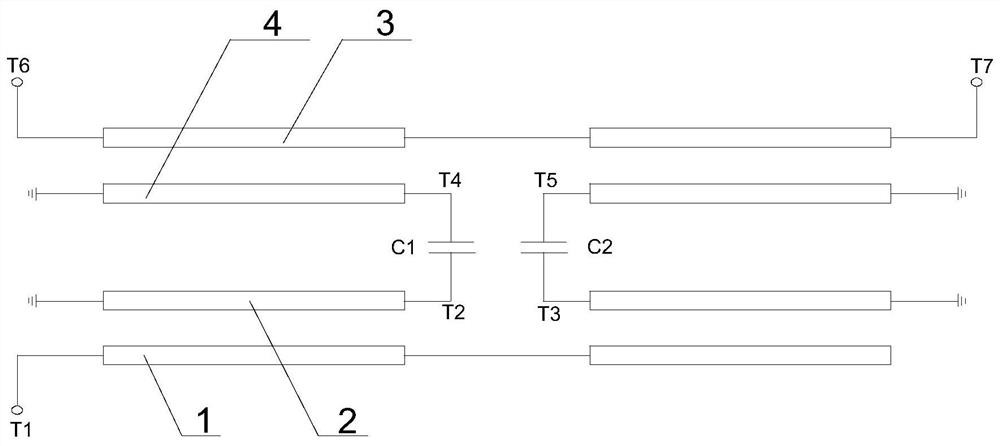
[0037] Such as Figure 1~4 As shown, the new broadband high-balance balun includes the first-stage balun that converts the unbalanced signal into a balanced signal, and the input terminal is connected to the output end of the first-stage balun and used to improve the output signal of the first-stage balun For the second-stage balun of balance, a phase compensation capacitor is connected between the first-stage balun and the second-stage balun in this embodiment. Among them, the output terminal of the first-stage balun includes output terminal T2 and output terminal T3, the input terminal of the second-stage balun includes input terminal T4 and input terminal T5, the phase compensation capacitor includes capacitor C1 and capacitor C2, and the output terminal T2 and The capacitor C1 is connected, the other end of the capacitor C1 opposite to the output terminal T2 is connected to the input terminal T4, the output terminal T3 is connected to the capacitor C2, and the other end of...

Embodiment 2

[0053] This embodiment makes the following further limitations on the basis of Embodiment 1: In this embodiment, when the transmission line I1, transmission line II3, coupled line I2, and coupled line II4 operate at a frequency within the range of 0.1 GHz to 14.1 GHz, The value of the length is 2940 μm.

[0054] 1. Verification and control test: In order to verify embodiment 2, the inventor adopted the structure and size of the traditional balun, the first-stage balun and the second-stage balun when the operating frequency was within the range of 0.1GHz to 14.1GHz The present invention of the uniform balun tests the transmission voltage waveform of each node signal, wherein the length of the balun in the present invention is set to 2940 μm, and this embodiment adopts HFSS or ADS electromagnetic field simulation software for simulation.

[0055] (1) Performance evaluation indicators: The key indicators of the balun include insertion loss, amplitude balance, phase balance and co...

Embodiment 3

[0058] This embodiment makes the following further limitations on the basis of Embodiment 1: In this embodiment, when the transmission line I1, transmission line II3, coupling line I2, and coupling line II4 are in the range of 18 GHz to 40 GHz, the length The value is 720 μm.

[0059] 1. Verification and comparison test: In order to verify embodiment 2, the inventors used the same structure and size for the traditional balun, the first-stage balun and the second-stage balun when the operating frequency was in the range of 18GHz to 40GHz The present invention of the balun tests the transmission voltage waveform of each node signal, wherein the length of the balun in the present invention is set to 720 μm, and this embodiment adopts HFSS or ADS electromagnetic field simulation software for simulation.

[0060] (1) Performance evaluation indicators: The key indicators of the balun include insertion loss, amplitude balance, phase balance and common-mode rejection ratio (CMRR). Th...


PUM


Abstract

The invention discloses a novel broadband high-balance-degree balun which comprises a first-stage balun for converting an unbalanced signal into a balanced signal, and a second-stage balun of which the input end is connected with the output end of the first-stage balun and which is used for improving the balance degree of an output signal of the first-stage balun, and a phase compensation capacitor is connected between the first-stage balun and the second-stage balun. By arranging the first-stage balun and the second-stage balun, the unbalanced signal is converted into a differential signal through the first-stage balun, and then the differential signal generated by the first-stage balun is improved through the second-stage balun so that the phase balance degree and the amplitude balance degree of the differential signal are improved; therefore, the phase difference of the finally output differential signals is closer to 180 degrees, and the amplitudes tend to be equal. The structure of the invention is suitable for various circuit applications, such as frequency mixers, duplexers and the like. In addition, based on the improved balun structure, a high-performance mixer, a high-performance duplexer and the like based on semiconductor material systems such as a silicon substrate, germanium-silicon, gallium arsenide and gallium nitride can be designed.

Description

technical field [0001] The invention relates to the technical field of integrated circuits, in particular to a novel broadband high-balance balun. Background technique [0002] The Barron has a long and illustrious history, being first documented in 1939 as a device that provided a television transmitting antenna for the Empire State Building. Today, the design of baluns has undergone tremendous changes, and its application fields are not only driving differential antennas, but also various types of balanced mixers, amplifiers, frequency multipliers, single-sideband modulators, etc., such as in In the application of a balanced mixer, since the balun has an even-order signal suppression function, it can be used to eliminate or greatly reduce the spurious signal in the mixer circuit, and at the same time reduce the leakage of the local oscillator signal to the RF and IF port energy. Additionally, there are several types of baluns, some of which are used for impedance transfo...

Claims


Application Information

Patent Timeline
Patent Type & Authority Applications(China)
IPC IPC(8): H03H7/42
CPCH03H7/42
Inventor 不公告发明人
Owner 成都芯川电子有限公司
Why Eureka
Try Eureka