A Constraint Release Type Differential Piezoelectric Ultrasonic Transducer Chip and Its Working Method

A piezoelectric ultrasonic and transducer technology, which is applied in the direction of sound-generating equipment, measuring ultrasonic/sonic/infrasonic waves, instruments, etc., can solve the problem of increasing the vibration amplitude of the transducer, increasing the output of useful signals, and increasing the sensitivity of the transducer and other problems, to achieve the effect of increasing the vibration amplitude, increasing the useful signal output, and reducing the residual stress

Active Publication Date: 2021-10-15
CHONGQING UNIV
View PDF5 Cites 0 Cited by
  • Summary
  • Abstract
  • Description
  • Claims
  • Application Information

AI Technical Summary

Problems solved by technology

[0004] The present invention intends to provide a constraint-releasing differential piezoelectric ultrasonic transducer chip and its working method, which can release the fixed constraints of the transducer vibration system, reduce residual stress, and increase the vibration amplitude of the transducer. Increase the useful signal output, increase the sensitivity of the transducer, and solve the problems of small vibration amplitude and low sensitivity in the prior art

Method used


Image

  • A Constraint Release Type Differential Piezoelectric Ultrasonic Transducer Chip and Its Working Method
  • A Constraint Release Type Differential Piezoelectric Ultrasonic Transducer Chip and Its Working Method
  • A Constraint Release Type Differential Piezoelectric Ultrasonic Transducer Chip and Its Working Method

Examples


Embodiment 1

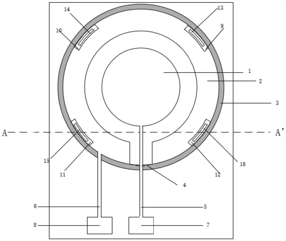
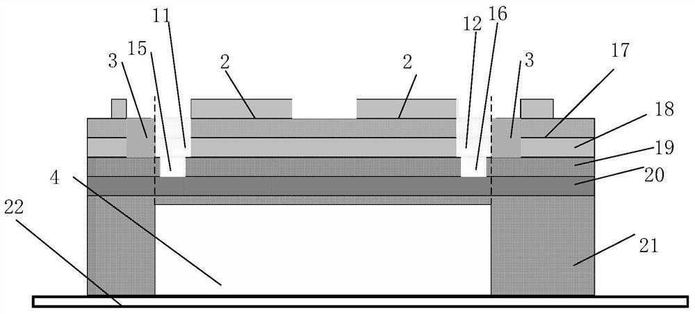
[0032] Such as figure 1 and figure 2 As shown, this embodiment discloses a constraint-releasing differential piezoelectric ultrasonic transducer chip, which includes a support layer, a bottom electrode 18 , a piezoelectric layer 17 and a top electrode in order from bottom to top. The support layer includes a base layer 21 , a stop layer 20 and an elastic layer 19 from bottom to top, and a cavity 4 is provided in the middle of the bottom of the base layer 21 corresponding to the central area of ​​the entire ultrasonic transducer chip. In this embodiment, the base layer 21 is disposed on the fixing plate 22 , the cavity 4 runs through the base layer 21 , and the cavity 4 is a circular cavity 4 .

[0033] The top electrode includes a top internal electrode 1 and a top external electrode 2 surrounding the top internal electrode 1. The top internal electrode 1 is connected to the top internal electrode lead-out interface 7 through the top internal electrode lead-out line 5, and t...

Embodiment 2

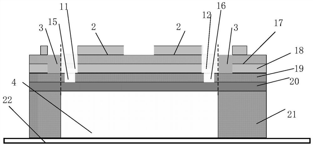
[0044] The difference between this embodiment and Embodiment 1 is that, if image 3 As shown, in this embodiment, the cavity 4 does not penetrate the base layer 21, that is, a layer of film support layer is formed on the top of the base layer 21. This method can improve the yield, and also improve the resistance of the device, and enhance the damage of the chip to the outside world. survivability under the action.

Embodiment 3

[0046] The difference between this embodiment and Embodiment 1 is that, if Figure 4 and Figure 5 As shown, in this embodiment, the mechanical slot group is arranged between the top inner electrode 1 and the top outer electrode 2 .


PUM


Abstract

The present invention relates to the technical field of ultrasonic detection, and specifically relates to a restraint release type differential piezoelectric ultrasonic transducer chip and its working method. The ultrasonic transducer chip includes a supporting layer, a bottom electrode, a piezoelectric layer and a For the top electrode, the piezoelectric layer is provided with an annular isolation groove downward at a position corresponding to the outer edge of the top electrode. The depth of the annular isolation groove is less than or equal to the sum of the heights of the piezoelectric layer and the bottom electrode. The support layer includes a base layer, a stop layer is arranged on the base layer, an elastic layer is arranged on the stop layer, and a cavity is opened upward at the bottom of the base layer. The cavities may or may not penetrate through the base layer. The constraint-releasing differential piezoelectric ultrasonic transducer chip and its working method of the present application can release the fixed constraints of the transducer vibration system, reduce the residual stress, and then increase the vibration amplitude of the transducer and increase the useful signal output, increase the sensitivity of the transducer, and solve the problems of small vibration amplitude and low sensitivity in the prior art.

Description

technical field [0001] The invention relates to the technical field of ultrasonic detection, in particular to a restraint release type differential piezoelectric ultrasonic transducer chip and a working method thereof. Background technique [0002] Ultrasonic testing technology belongs to acoustic sensing testing technology, which mainly uses ultrasonic waves for material testing. It is one of the five conventional nondestructive testing methods. It refers to the good characteristics of ultrasonic propagation in the medium, strong reflection ability, easy to obtain concentrated sound energy, low propagation attenuation, large energy contained in ultrasonic waves, and harmless to the human body. , non-destructive testing, underwater communication, fingerprint sensing, smart home and other fields of detection technology. As the main component of a high-end ultrasonic non-destructive testing instrument, the piezoelectric ultrasonic transducer is used to convert electric energy...

Claims


Application Information

Patent Timeline
Patent Type & Authority Patents(China)
IPC IPC(8): B06B1/06G10K9/122G01H11/08
CPCB06B1/0662G01H11/08G10K9/122
Inventor 牟笑静周雪梅易拥洁蔡贵祥黄河
Owner CHONGQING UNIV
Why Eureka
Try Eureka