Titanium alloy compressor rotor blade tip repairing method and repairing tool

A technology of a compressor rotor and a repair method, which is applied in the directions of additive processing, process efficiency improvement, energy efficiency improvement, etc., can solve the problems of difficult positioning of parts, interference in equipment process, etc., and achieves small machining allowance, Improve repair performance and efficiency, fine grain effect

Active Publication Date: 2020-12-15
AVIC BEIJING INST OF AERONAUTICAL MATERIALS
View PDF4 Cites 5 Cited by
  • Summary
  • Abstract
  • Description
  • Claims
  • Application Information

AI Technical Summary

Problems solved by technology

However, selective laser melting (SLM) and electron beam selective melting (EBM) are processes used to directly manufacture parts. There is no method for repairing parts before. To use them for blade tip repair needs to overcome many difficulties: the clamping of parts Difficulty

Method used


Image

  • Titanium alloy compressor rotor blade tip repairing method and repairing tool
  • Titanium alloy compressor rotor blade tip repairing method and repairing tool
  • Titanium alloy compressor rotor blade tip repairing method and repairing tool

Examples


specific example 1

[0051] EOS M290 laser selective melting (SLM) equipment was used to repair the wear damage of the TC4 titanium alloy rotor blade tip of a certain type of engine compressor. The specific steps are as follows:

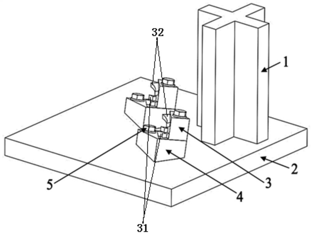
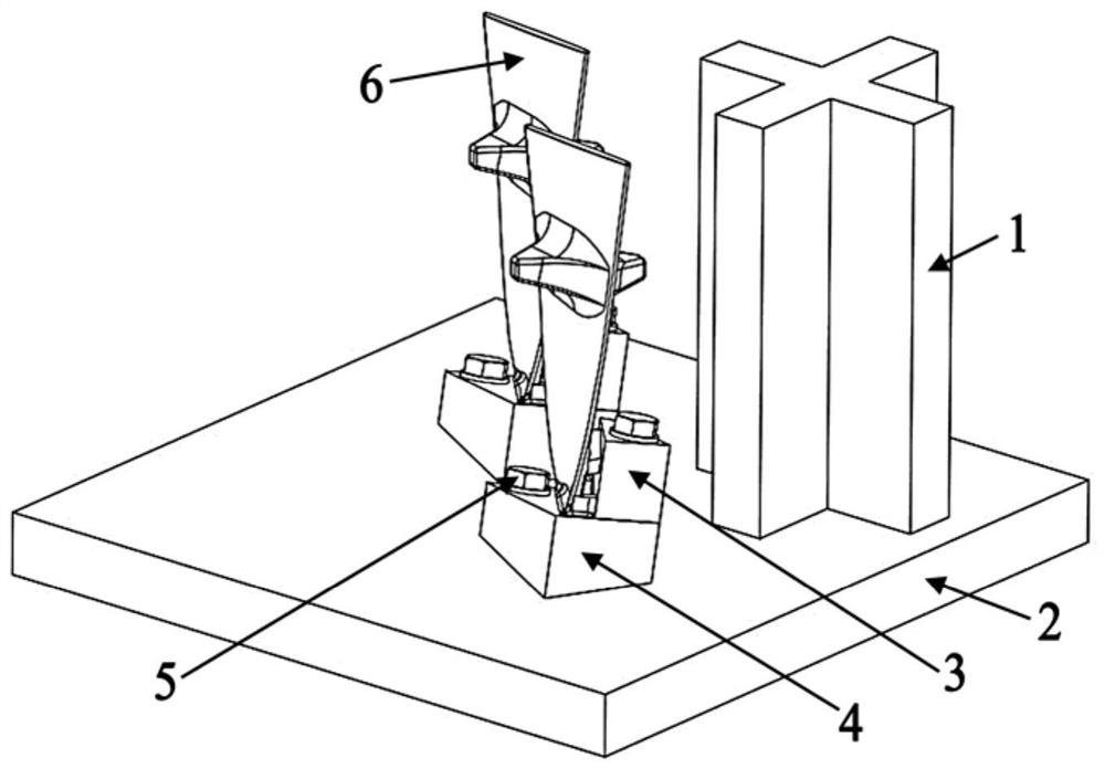
[0052] S1. Tooling design and blade clamping: Design a tooling to assist compressor blade positioning, clamping and laser selective melting (SLM) repair. For the designed tooling shape and clamping method, see figure 1 with figure 2 .

[0053] see Figure 1 to Figure 5 , The tooling designed in the present invention includes a cross base block 1, a base plate base 2, a locking block 3, a bottom cushion block 4 and a bolt 5.

[0054] The size of the cross base block 1 is 100mm (cross length) × 30mm (cross width) × 120mm (cross height), which is welded on the base surface of the substrate, see figure 1 with figure 2 .

[0055] The size of the substrate base 2 is 252mm (length) × 252mm (width) × 20mm (thickness). There are M5 threaded holes in the substrate base, wh...

specific example 2

[0072] Using Arcam A2X Electron Beam Selective Melting (EBM) equipment to repair the wear damage of the blade tip of a TC4 titanium alloy compressor blade of a certain type of engine, the specific steps are as follows:

[0073] S1. Tooling design and blade clamping: Design a tooling to assist compressor blade positioning, clamping and electron beam melting (EBM) repair. For the designed tooling shape and clamping method, see figure 1 with figure 2 .

[0074] see Figure 1 to Figure 4 , The tooling designed in the present invention includes a cross base block 1, a base plate base 2, a locking block 3, a bottom cushion block 4 and a bolt 5.

[0075] The size of the cross base block 1 is 100mm (cross length) × 30mm (cross width) × 120mm (cross height), which is welded on the base surface of the substrate, see figure 1 with figure 2 .

[0076] The size of the substrate base 2 is 252mm (length) × 252mm (width) × 25mm (thickness). There are M5 threaded holes in the substrate...


PUM

PropertyMeasurementUnit
Granularityaaaaaaaaaa
Thicknessaaaaaaaaaa
Granularityaaaaaaaaaa

Abstract

The invention belongs to the technical field of aero-engine maintenance, and relates to a titanium alloy compressor rotor blade tip repairing method and a repairing tool. According to the method, repairing is completed by adopting a laser selective melting or electron beam selective melting process, a blade can be placed in a forming area of laser selective melting or electron beam selective melting equipment by means of the tool and is formed at the blade tip, data are obtained through three-dimensional scanning for reverse modeling to obtain a model needing to be repaired and formed and related position information, the corresponding tool and blade clamping are designed, the structure and the form are not limited, and the tool can be used for completing blade clamping, auxiliary positioning and position calibration; printing, repairing and forming are carried out after positioning and calibration, and finally post-processing and detection are completed; and the positioning precisionof blade repairing is well controlled, and the method has the advantages of being small in heat input, fine in grain, good in mechanical property, small in deformation, good in surface roughness, highin size precision, free of machining in near-net forming, rapid and efficient in forming and the like.

Description

technical field [0001] The invention belongs to the technical field of aero-engine maintenance, and relates to the repair of key components of the engine, in particular to a method for repairing the blade tip of a titanium alloy compressor rotor blade and repair tooling, and in particular to a laser selection area for the blade tip of a titanium alloy compressor rotor blade Melting (SLM) and Electron Beam Selective Melting (EBM) restoration methods and tooling for restoration. Background technique [0002] Titanium alloy compressor rotor blades are rotating at high speed in a high-pressure flow environment. The gas pressure at the blade tip is the highest and the air velocity is very high, which makes the blade tip prone to wear and tear, and repairs are generally required every time it is overhauled. The traditional repair method is to use welding techniques such as argon arc welding or laser welding to surfacing welding on the top of the blade, and then perform machining a...

Claims


Application Information

Patent Timeline
IPC IPC(8): B22F3/105B22F3/24B22F7/06B33Y10/00B33Y30/00B33Y50/02B33Y80/00
CPCB22F3/003B22F3/24B22F7/062B33Y10/00B33Y30/00B33Y50/02B33Y80/00B22F2003/247B22F2007/068Y02P10/25
Inventor 张学军赵海生秦仁耀张强孙兵兵
Owner AVIC BEIJING INST OF AERONAUTICAL MATERIALS
Why Eureka
Try Eureka