Automatic slitting equipment for pipes

A pipe and automatic technology, applied in metal processing and other directions, can solve the problems of low degree of automation and processing efficiency, pipe damage, simple structure, etc., and achieve the effect of improving processing efficiency, reducing scrap rate and simple structure.

Inactive Publication Date: 2020-12-15
GUANGZHOU ZHI JIAN GENERAL EQUIP MFG CO LTD
View PDF6 Cites 5 Cited by
  • Summary
  • Abstract
  • Description
  • Claims
  • Application Information

AI Technical Summary

Problems solved by technology

Due to the concentration of force, this cutting method is prone to chipping on the cross section of the pipe. The chipping phenomenon refers to the phenomenon that grooves or notches are formed on the cross section of the pipe due to the concentration of force, resulting in damage to the pipe.
In particular, for some paper tubes with high hardness, their toughness is relatively low. When the above-mentioned slitting machine is used for slitting, edge chipping occurs more frequently, resulting in a higher scrap rate of slitting
On the other hand, the slitting machine in the prior art has simple structure, low degree of automation and processing efficiency

Method used


Image

  • Automatic slitting equipment for pipes
  • Automatic slitting equipment for pipes
  • Automatic slitting equipment for pipes

Examples


Embodiment Construction

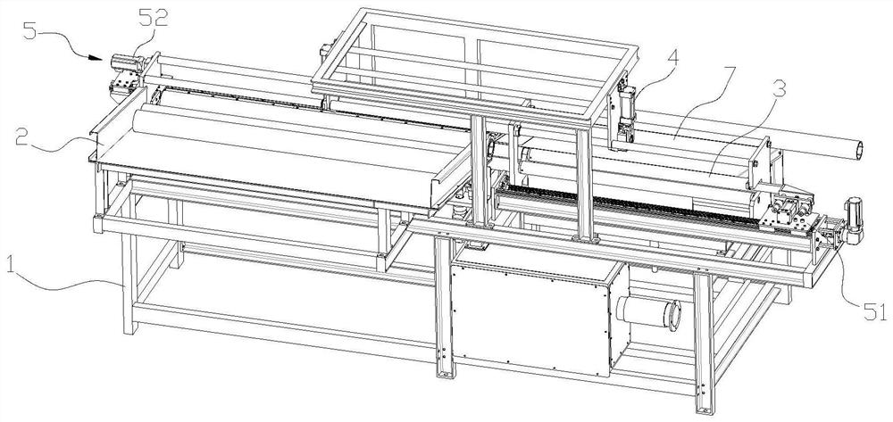
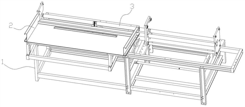
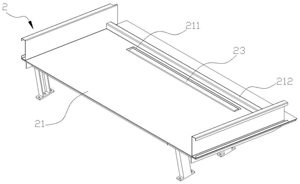
[0071] Such as figure 1 As shown, an automatic pipe cutting device according to the present invention includes a control system, a frame 1 , a feeding mechanism 2 and a backup roller mechanism 3 arranged on the frame 1 . A pinch roller mechanism 4, a feeding mechanism 5, a material cutting mechanism 6 and a blanking mechanism 7.

[0072] see figure 1 , frame 1 is welded by steel plates, extending from left to right (with figure 1 The direction shown is an example), and the overall shape is approximately cuboid.

[0073] The backup roller mechanism 3 is arranged in the middle of the frame 1 and extends along the length direction of the frame 1, that is, the axial direction of the backup roller mechanism 3 is from left to right. The supporting roller mechanism 3 is used to support and drive the pipe to rotate synchronously. When the supporting roller mechanism 3 supports the pipe, its outer peripheral surface contacts with the outer peripheral surface of the pipe, and drives ...


PUM


Abstract

The invention discloses automatic slitting equipment for pipes, and relates to the technical field of pipe processing. The automatic slitting equipment comprises a control system and a rack and further comprises a feeding mechanism, a bearing roller mechanism, a clamping roller mechanism, a conveying mechanism, a cutting mechanism and a discharging mechanism which are arranged on the rack; the bearing roller mechanism is used for bearing and driving pipes to synchronously rotate; the bearing roller mechanism is sequentially provided with a feeding station and a cutting station in the length direction of the bearing roller mechanism; the feeding mechanism is used for conveying the pipes to the feeding station; the conveying mechanism is used for conveying the pipes from the feeding stationto the cutting station; the clamping roller mechanism is used for being matched with the bearing roller mechanism to jointly clamp the pipes; the cutting mechanism is used for cutting off the pipes; the discharging mechanism is used for moving the cut-off pipes out of the cutting station; and a control system is used for controlling operation of all the mechanisms. The pipes are synchronously rotated during tool feeding of a tool, so that the pipes are stressed uniformly, the edge breakage probability is greatly reduced, the rejection rate is decreased, the processing efficiency is improved, and the automation degree is high.

Description

technical field [0001] The invention relates to the technical field of pipe processing, in particular to an automatic cutting device for pipes. Background technique [0002] Pipe slitting is one of the processes of pipe processing. Specifically, the pipe is cut into pipe sections of various lengths according to processing requirements. In the prior art, this process is usually completed with equipment such as a slitting machine. The pipe is fixed on the slitting machine, the knife is approached and cut off the pipe, the knife is retracted after cutting, and the pipe is cut into required lengths of pipe sections repeatedly. [0003] In the prior art, when the slitting machine cuts the pipe, it feeds the knife along the radial direction of the pipe. Since the pipe is in a fixed state, the cutting force exerted by the cutter on the feeding position is relatively large and concentrated in the local area when the pipe is in a fixed state. . Due to the concentration of force, th...

Claims


Application Information

Patent Timeline
Patent Type & Authority Applications(China)
IPC IPC(8): B26D3/11B26D5/08B26D7/06B26D7/01B26D7/02B26D7/18
CPCB26D3/11B26D5/086B26D7/01B26D7/02B26D7/0608B26D7/0641B26D7/1818B26D7/1863B26D2007/013
Inventor 徐阳陈凯
Owner GUANGZHOU ZHI JIAN GENERAL EQUIP MFG CO LTD
Why Eureka
Try Eureka