A Nucleus Manipulation Method Based on Dynamic Nucleus Position Drift Modeling

A technology of dynamic drift and operation method, applied in the direction of stress-stimulated microbial growth, biochemical equipment and method, biochemical cleaning device, etc., can solve problems such as difficult to control the movement of microneedles, and meet the requirements of simple experimental equipment and cytoplasmic The effect of reducing the amount of removal and increasing the cleavage rate of pig cloned embryos

Active Publication Date: 2021-10-01
NANKAI UNIV
View PDF9 Cites 0 Cited by
  • Summary
  • Abstract
  • Description
  • Claims
  • Application Information

AI Technical Summary

Problems solved by technology

[0004] Aiming at the problem that it is difficult to control the microneedle to move to a suitable position near the nucleus to operate the nucleus in the existing cell nucleus operation method, the present invention proposes a cell nucleus operation method based on the dynamic drift modeling of the cell nucleus position. Determine the three-dimensional distribution range of the nucleus relative to the polar body to estimate the initial position range of the nucleus, obtain the dynamic drift trajectory of the nucleus position and its dominant influencing factors through three-dimensional finite element modeling and factorial design, and fit the parameters of the intracellular movement trajectory of the microneedle The curve relationship with the dynamic drift trajectory parameters of the nucleus position determines the microneedle trajectory required to move the microneedle to a suitable position near the nucleus to operate the nucleus, and finally controls the movement of the intracellular microneedle to move along the set trajectory to a predetermined position to complete the nucleus operate

Method used


Image

  • A Nucleus Manipulation Method Based on Dynamic Nucleus Position Drift Modeling
  • A Nucleus Manipulation Method Based on Dynamic Nucleus Position Drift Modeling
  • A Nucleus Manipulation Method Based on Dynamic Nucleus Position Drift Modeling

Examples


Embodiment 1

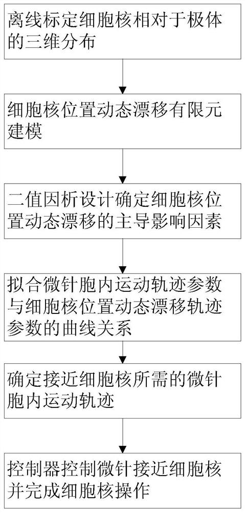
[0038] Embodiment 1: as figure 1 As shown in the flow chart of , a cell nucleus operation method based on dynamic drift modeling of cell nucleus position, the method includes the following steps:

[0039] S1, three-dimensional positioning of fluorescently stained cell nuclei under off-line conditions, and compared with the three-dimensional position of polar bodies determined under bright field, to determine the three-dimensional distribution of cell nuclei relative to polar bodies;

[0040] S2, when the microneedle moves in the cell through three-dimensional finite element modeling, the dynamic drift trajectory of the cell nucleus relative to the position of the microneedle caused by cell deformation;

[0041] S3, using the binary factorial design method to determine the dominant factors affecting the dynamic drift trajectory of the nucleus position when the microneedle moves in the cell;

[0042] S4, fitting the relationship curve between the microneedle intracellular traje...


PUM


Abstract

The invention relates to a cell nucleus operation method based on the dynamic drift modeling of the cell nucleus position, comprising the following steps: off-line calibration of the three-dimensional distribution of the cell nucleus relative to a polar body; obtaining the dynamic drift track of the cell nucleus relative to the position of a microneedle through three-dimensional finite element modeling; The factorial design method is used to determine the dominant influencing factors of the dynamic drift of the nucleus position; the relationship between the intracellular movement parameters of the microneedle and the dynamic drift trajectory parameters of the nucleus position is fitted to determine the trajectory of the microneedle required to approach the nucleus, and the microneedle is controlled by the controller. The needle moves in the cell along the determined trajectory and approaches the nucleus and completes the corresponding operations. Using the method for operating the nucleus of the present invention, the enucleation operation can automatically control the trajectory of intracellular movement and the removal amount of cytoplasm. Compared with manual enucleation, the amount of cytoplasm removed is reduced by 60% under the same enucleation success rate, and the cleavage rate of pig cloned embryos is nearly doubled.

Description

technical field [0001] The invention belongs to the field of cell-level micromanipulation, and in particular relates to a cell nucleus operation method based on dynamic drift modeling of cell nucleus position. Background technique [0002] Oocyte nuclear manipulation is widely used in operations such as animal cloning and nuclear transgene injection. The premise of operating the oocyte nucleus is: move the operating tool such as a microneedle to a position suitable for operating the nucleus near the nucleus, and then perform subsequent operations. However, this task is difficult to accomplish because the oocyte nucleus is generally invisible, and the movement of the microneedles in the cell will cause cell deformation and cause dynamic drift of the nucleus position. [0003] Although the cell nucleus can be manipulated by staining the cell nucleus, the cell nucleus positioning and the movement control of the microneedle will not only be damaged due to the photobleaching und...

Claims


Application Information

Patent Timeline
Patent Type & Authority Patents(China)
IPC IPC(8): C12M1/00C12M1/36C12M1/34G16B15/00
CPCC12M35/04C12M41/00G16B15/00
Inventor 赵启立赵新邱金禹孙明竹韩宇贾祎晴
Owner NANKAI UNIV
Why Eureka
Try Eureka