Heat exchange tube, heat exchanger tube core, heat exchanger and manufacturing method

A heat exchanger tube, heat exchange tube technology, applied in the heat exchanger tube core, heat exchange tube, heat exchanger and manufacturing fields, can solve the problem of affecting the heat exchange effect and service life of the heat exchanger, waste of high temperature flue gas waste heat , corrosion of metal heat exchange tubes, etc., to reduce the possibility of dew point corrosion, increase the heat exchange area, and avoid stress deformation.

Pending Publication Date: 2020-12-15
洛阳超蓝节能技术有限公司 +2
View PDF0 Cites 1 Cited by
  • Summary
  • Abstract
  • Description
  • Claims
  • Application Information

AI Technical Summary

Problems solved by technology

However, taking the practical application of heat exchange between acidic high-temperature flue gas and low-temperature medium as an example, the acidic high-temperature flue gas goes through the shell side, and the low-temperature medium goes through the tube side. Near the flue gas outlet, the temperature of the high-temperature flue gas decreases after heat exchange. In the tube at the corresponding position is the low-temperature medium that has just flowed into the heat exchanger, resulting in a low wall temperature of the heat exchange tube at the outlet of the flue gas
Because the acidic high-temperature flue gas contains acidic and corrosive gas components, such as sulfur dioxide, when the temperature is lower than its acid dew point corrosion temperature, it will corrode the metal heat exchange tubes, causing some heat exchange tubes to corrode, perforate and leak, affecting the heat exchange rate. The heat exchange effect and service life of the heater, but if the exhaust gas temperature is increased to avoid dew point corrosion, it will cause waste of high-temperature flue gas waste heat

Method used


Image

  • Heat exchange tube, heat exchanger tube core, heat exchanger and manufacturing method
  • Heat exchange tube, heat exchanger tube core, heat exchanger and manufacturing method
  • Heat exchange tube, heat exchanger tube core, heat exchanger and manufacturing method

Examples


Embodiment Construction

[0060] The application will be further described in detail below in conjunction with the accompanying drawings and embodiments. It should be understood that the specific embodiments described here are only used to explain related inventions, rather than to limit the invention. It should also be noted that, for ease of description, only parts related to the invention are shown in the drawings.

[0061] In the present invention, the orientation or positional relationship indicated by the terms "upper", "lower", "inner", "outer", "center", "longitudinal", "axial" etc. are based on the orientation or positional relationship shown in the drawings Positional relationship. These terms are mainly used to better describe the present invention and its embodiments, and are not intended to limit that the indicated device, element or component must have a specific orientation, or be constructed and operated in a specific orientation.

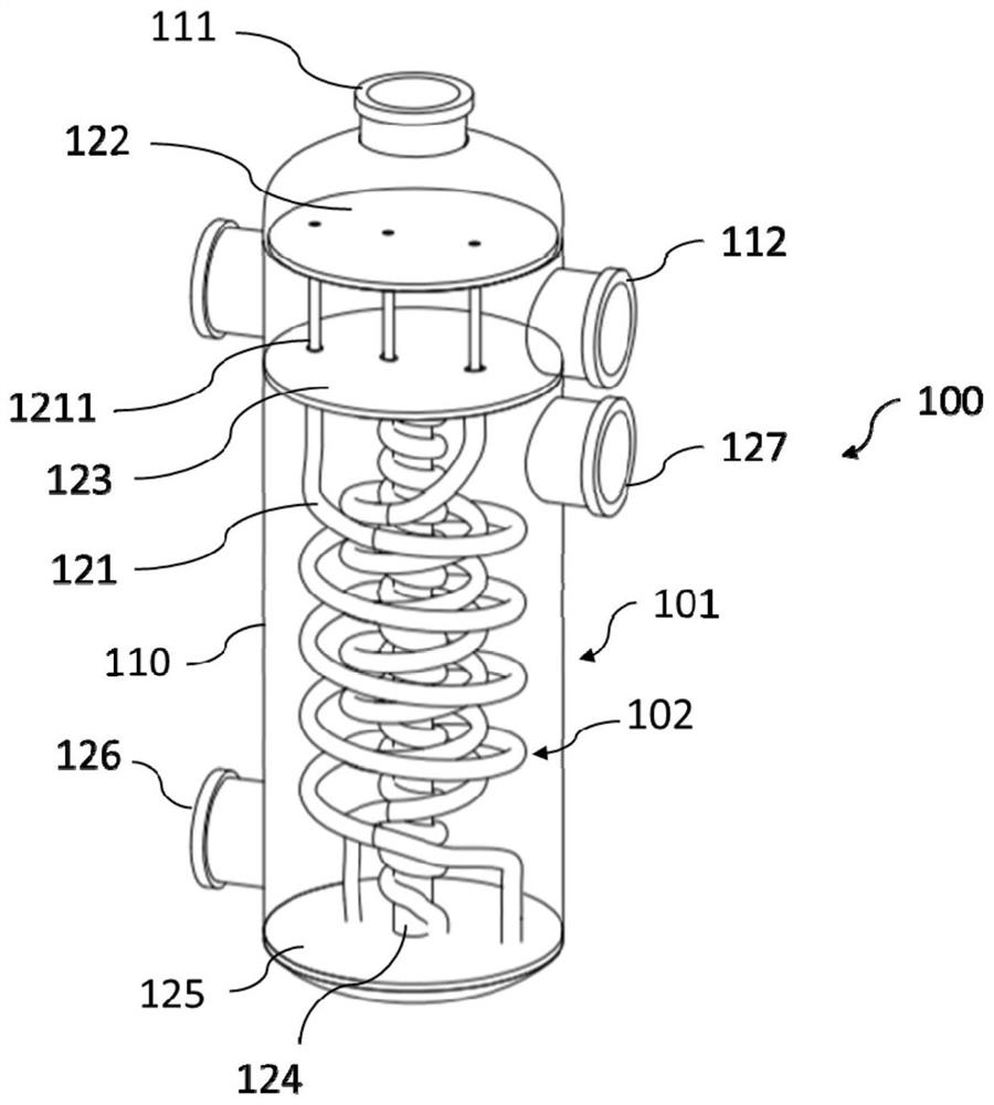
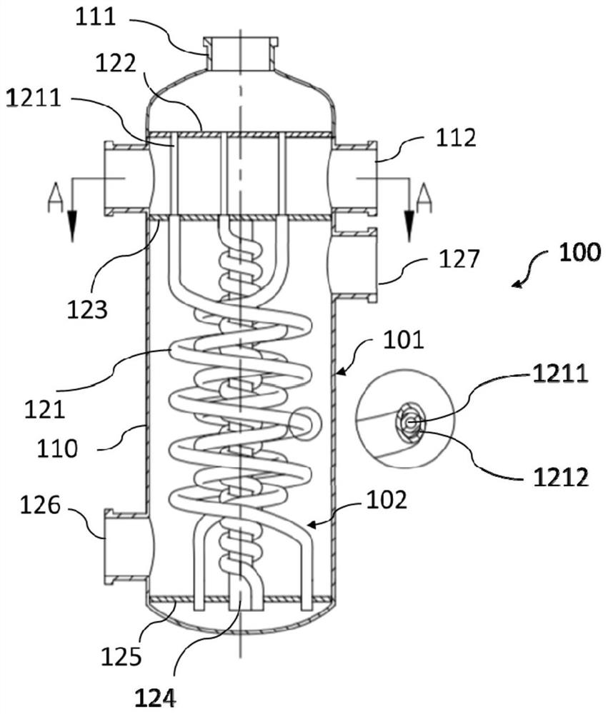
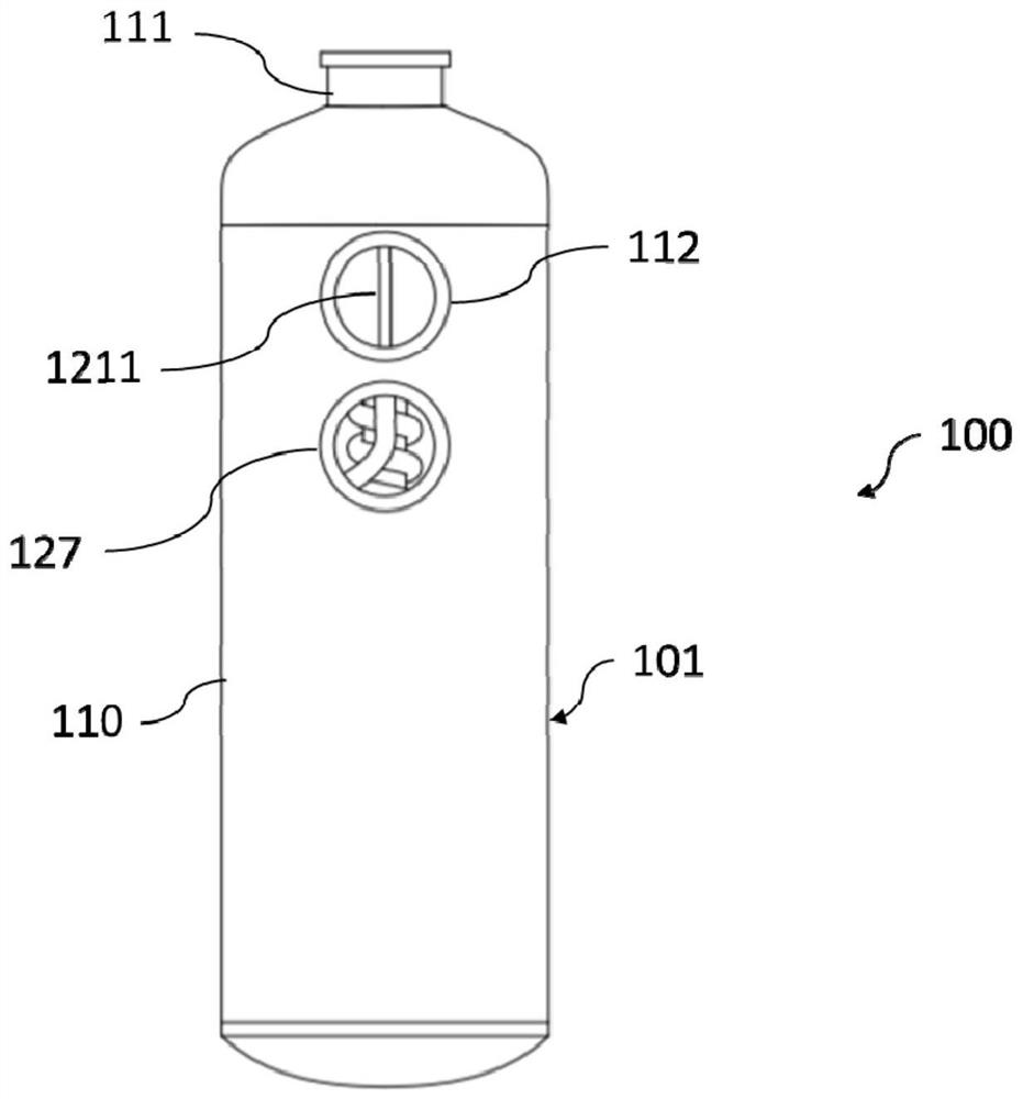
[0062] figure 1 It is a perspective view of the hea...


PUM


Abstract

The application discloses a heat exchange tube comprising a first hollow tube and a second hollow tube, and the first hollow tube comprises a first end and a second end; the second hollow pipe comprises an open end and a closed end, and the first hollow tube is arranged in the second hollow tube; a gap is formed between the outer wall of the first hollow tube and the inner wall of the second hollow tube, and the first end of the first hollow tube extends out of the open end of the second hollow tube; the second end of the heat exchange tube is separated from the inner wall of the closed end ofthe second hollow tube; and the open end of the second hollow tube of the heat exchange tube and the middle part of the second end of the first hollow tube are wound into a spiral shape around a center. The application further discloses a heat exchanger tube core using the heat exchange tube, a heat exchanger and a manufacturing method thereof. By adopting the spiral winding type and sleeve typeheat exchange tubes, the heat exchange area can be increased, so that the heat exchange efficiency is improved; meanwhile, stress deformation and weld joint cracking due to heat expansion of the heatexchange tubes in use of the heat exchanger tube core and the heat exchanger are avoided; and the possibility of dew point corrosion can be reduced.

Description

technical field [0001] The invention relates to the field of waste heat recovery in industries such as oil refining and chemical industry, and in particular relates to an improved heat exchange tube, a heat exchanger core, a heat exchanger and a manufacturing method for improving heat exchange efficiency. Background technique [0002] The countercurrent spiral wound tube heat exchanger has high heat exchange efficiency and is widely used in various fields. However, taking the practical application of heat exchange between acidic high-temperature flue gas and low-temperature medium as an example, the acidic high-temperature flue gas goes through the shell side, and the low-temperature medium goes through the tube side. Near the flue gas outlet, the temperature of the high-temperature flue gas decreases after heat exchange. In the tube at the corresponding position is the low-temperature medium that has just flowed into the heat exchanger, resulting in a low wall temperature o...

Claims


Application Information

Patent Timeline
IPC IPC(8): F28D7/02F28F1/02F28F9/02F28F9/24F28F11/00F28F19/00
CPCF28D7/024F28F1/02F28F9/0229F28F9/24F28F11/00F28F19/00
Inventor 程向锋武立国杨芳张国萍于景发吕金豹张新民王佳陈霄
Owner 洛阳超蓝节能技术有限公司
Why Eureka
Try Eureka