
Low-frequency remote three-dimensional imaging method based on acoustic orbital angular momentum

An orbital angular momentum, three-dimensional imaging technology, applied in the field of marine acoustic equipment, can solve the problems of complex hardware system, inability to detect distance, and high research and development threshold, achieve high detection accuracy and improve imaging resolution.

Pending Publication Date: 2020-12-15
天津水聿方舟海洋工程技术有限公司
View PDF0 Cites 10 Cited by
  • Summary
  • Abstract
  • Description
  • Claims
  • Application Information

AI Technical Summary

Problems solved by technology

This type of three-dimensional imaging sonar has been developed by the United States, the United Kingdom, and Norway. The working distance can cover hundreds of meters, but the research and development threshold is high, and it faces some bottleneck problems: (1) The hardware system is extremely complex, requiring thousands of Transducers and signal processing circuits are difficult to realize in terms of technology; (2) The imaging resolution is 1-2 orders of magnitude lower than that of optical imaging, and it is difficult to further improve due to the limitation of the aperture size of the sonar carrier; (3) The imaging angle of view is limited Limited to algorithmic limitations, it is difficult to effectively expand
However, the higher the frequency of the detection sound wave, the faster the attenuation in water and the shorter the propagation distance. Therefore, in order to ensure the detection accuracy, it is impossible to detect a longer distance

Method used


Image

  • Low-frequency remote three-dimensional imaging method based on acoustic orbital angular momentum
  • Low-frequency remote three-dimensional imaging method based on acoustic orbital angular momentum
  • Low-frequency remote three-dimensional imaging method based on acoustic orbital angular momentum

Examples


Embodiment Construction

[0033] Embodiments of the present invention are described in further detail below in conjunction with the accompanying drawings:

[0034] A low-frequency remote three-dimensional imaging method based on acoustic orbital angular momentum, comprising the following steps:

[0035] Step 1. Build an acoustic orbital angular momentum super-resolution three-dimensional imaging sonar.

[0036] The acoustic orbital angular momentum super-resolution three-dimensional imaging sonar consists of a transducer array and a signal processing circuit board. Such as figure 1 As shown, the transducer array includes a ring array and a spiral array, and the ring array is arranged at equal intervals on a circle with a radius a N independent sending and receiving and displacing transducers; The spiral array is set in the circular array, and the spiral array is to arrange M receiving transducers spirally in the garden with a radius of a; with the center of the circle as the coordinate origin, all t...


PUM


Abstract

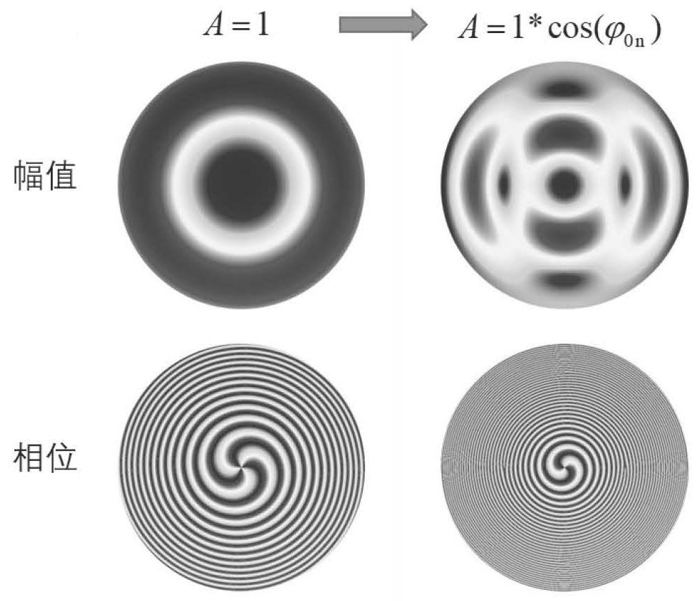
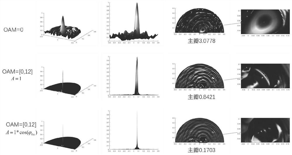
The invention relates to a low-frequency remote three-dimensional imaging method based on acoustic orbital angular momentum. The method comprises the following steps of: constructing an acoustic orbital angular momentum super-resolution three-dimensional imaging sonar; emitting a vortex sound field which is non-uniformly distributed in the circumferential direction by the acoustic orbital angularmomentum super-resolution three-dimensional imaging sonar and receiving echo signals reflected by a remote target; respectively carrying out primary beam forming on a pitch angle and an azimuth angleto obtain a series of two-dimensional sonar image slices in the area, and synthesizing the series of slices in the distance direction to obtain three-dimensional sonar imaging; and respectively carrying out secondary beam forming on the pitch angle and the azimuth angle to obtain a super-resolution three-dimensional image. According to the invention, high detection precision can be generated by using low detection sound wave frequency, the imaging resolution can be improved, and the difficulty of short detection distance caused by the condition that the higher the detection sound wave frequency is and the faster the attenuation of the detection sound wave in water is can be overcome.

Description

technical field [0001] The invention belongs to the technical field of marine acoustic equipment, and relates to a three-dimensional imaging sonar technology, in particular to a low-frequency remote three-dimensional imaging method based on acoustic orbital angular momentum. Background technique [0002] The high-precision three-dimensional detection technology of underwater targets has very urgent application requirements in national defense and military fields such as port and navigation safety, underwater engineering, emergency rescue, and underwater vehicle confrontation. However, due to the serious propagation attenuation of electromagnetic waves in the water environment, the common optical and electromagnetic detection technologies on land and in the air have low usability underwater. Underwater 3D sonar imaging technology is one of the most important innovations in various sea-related industries in recent years. It can conduct multi-angle, high-resolution continuous o...

Claims


Application Information

Patent Timeline
IPC IPC(8): G01S15/89
CPCG01S15/89
Inventor 李胜全葛铮曹津舫夏启兵
Owner 天津水聿方舟海洋工程技术有限公司
Learn More