Anti-friction bearing having an integrated current-removal function

A rolling bearing and rolling element technology, applied in rolling contact bearings, rotating bearings, bearings, etc., can solve problems such as carbon fiber position uncertainty, fiber breakage, and copper brush replacement.

Active Publication Date: 2020-12-15
SCHAEFFLER TECH AG & CO KG
View PDF14 Cites 0 Cited by
  • Summary
  • Abstract
  • Description
  • Claims
  • Application Information

AI Technical Summary

Problems solved by technology

[0008] However, the known solutions have the disadvantage that wear occurs on the copper brushes, which reduces the service life of the rolling bearing or requires replacement of the copper brushes; or in the case of solutions using individual fine carbon fibers, fiber breakage or Risk of indeterminate position of the carbon fiber relative to the corresponding opposing rolling bearing ring or shaft
Solutions with carbon fiber composite components are more complex to assemble and are therefore correspondingly more expensive

Method used


Image

  • Anti-friction bearing having an integrated current-removal function
  • Anti-friction bearing having an integrated current-removal function
  • Anti-friction bearing having an integrated current-removal function

Examples


Embodiment Construction

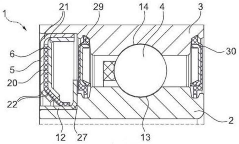
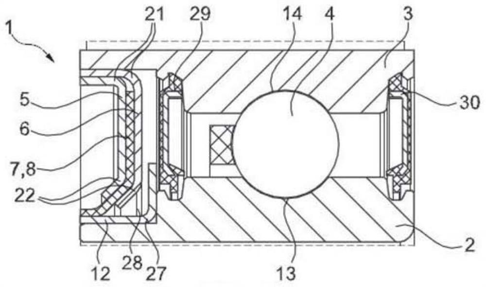
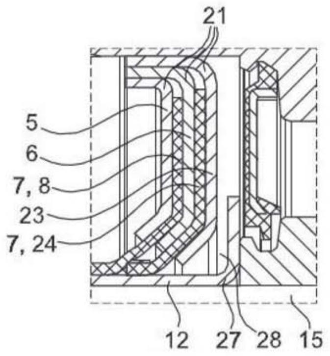
[0032] figure 1 An exemplary embodiment of a rolling bearing 1 according to the invention for use on an electric motor, in particular for supporting a shaft 15 , in particular a drive shaft of the electric motor, is shown with an integrated current elimination function. The rolling bearing 1 comprises an inner ring 2 and an outer ring 3, which are rotatable relative to each other. For this purpose, raceways 13 , 14 are formed on the inner ring 2 and the outer ring 3 , in which rolling bodies 4 , in particular balls or rollers, are guided. The inner ring 2 is carried by the drive shaft of the electric motor and is non-rotatably connected to this shaft 15 . For this purpose, the inner ring 2 can in particular be pressed onto the shaft 15 . The outer ring 3 is arranged in the housing of the electric motor and is non-rotatably connected to the housing. Two plates 5 , 6 are pressed into the outer ring 3 of the rolling bearing 1 , between which a conductive element 7 is clamped. ...


PUM


Abstract

The invention relates to an anti-friction bearing (1) for rotatably mounting a shaft (15), having an inner ring (2) with a first raceway (13) for a rolling body (4), having an outer ring (3) with a second raceway (14) for a rolling body (4), and rolling bodies (4) which are arranged between the raceways (13, 14) of the bearing rings (2, 3). It is provided that at least two plates (5, 6) are fastened to a first one of the bearing rings (2, 3), wherein an electrically conducting element (7) is arranged between the two plates (5, 6), which electrically conducting element (7) bears against the respective other bearing ring (2, 3) or a component (12, 15) which is connected to the respective other bearing ring (2, 3). Furthermore, the invention relates to a method for producing an anti-frictionbearing of this type, wherein an electrically conducting element (7) is clamped in between the two plates (5, 6), wherein an opening (10) is made in the electrically conducting element (7) which is clamped in between the plates (5, 6), and wherein the two plates (5, 6) are fastened to one of the bearing rings (2, 3) of the anti-friction bearing (1).

Description

technical field [0001] According to the preambles of the independent claims, the invention relates to a rolling bearing with an integrated current elimination function and to a method for producing such a rolling bearing. Background technique [0002] Rotary shafts such as turbines, electric motors or other shafts are known from the prior art which are electrically conductively connected to components to which voltage is introduced or in which voltage can accumulate during operation. Such a build-up of voltage is known, especially in the case of drive shafts of AC motors, whereby a high voltage may develop between a live part and another part. As the motor operates, the electrical resistance in the bearings increases, thereby generating an electric charge on the surface of the rotating shaft. This can result in a high voltage difference that discharges on the electrical path of least resistance. This electrical discharge may result in an electrical spark that causes corros...

Claims


Application Information

Patent Timeline
Patent Type & Authority Applications(China)
IPC IPC(8): F16C19/52F16C19/06F16C33/78
CPCF16C19/06F16C19/52F16C33/7823F16C33/784F16C33/7856F16C33/7886F16C41/002F16C2202/32
Inventor 亚历山大·沙米恩
Owner SCHAEFFLER TECH AG & CO KG
Why Eureka
Try Eureka