Automatic wood slicing device for building materials

A slicing device, wood technology, applied in the direction of clamping device, feeding device, wood processing equipment, etc., can solve the problems of inconvenient operation, low efficiency, easy injury, etc., and achieve the effect of preventing unevenness

Active Publication Date: 2020-12-18
蓝山县奔嘉木业有限公司
View PDF12 Cites 17 Cited by
  • Summary
  • Abstract
  • Description
  • Claims
  • Application Information

AI Technical Summary

Problems solved by technology

[0005] In order to overcome the disadvantages of inconvenient operation, low efficiency and easy injury, the technical problem of the present invention

Method used


Image

  • Automatic wood slicing device for building materials
  • Automatic wood slicing device for building materials
  • Automatic wood slicing device for building materials

Examples


Embodiment 1

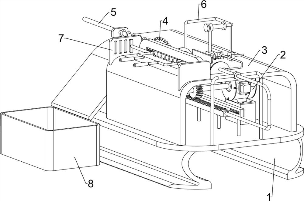
[0023] A kind of timber automatic slicing device for building materials, such as figure 1 , figure 2 and Figure 5 As shown, it includes a first workbench 1, a motor 2, a second workbench 3, an electric saw 4, a pushing mechanism 5 and a pressing mechanism 6, and the upper right side of the first workbench 1 is provided with a motor 2, and the first workbench 1 is provided with a second workbench 3 , a chainsaw 4 is rotatably provided on the second workbench 3 , a pushing mechanism 5 is provided on the first workbench 1 , and a pressing mechanism 6 is provided on the second workbench 3 .

[0024] When people prepare to slice the wooden block, the wooden block is first placed on the second workbench 3, then the motor 2 is started, and the output shaft of the motor 2 will drive the pushing mechanism 5 to rotate, and the pushing mechanism 5 will push the wooden block To the chainsaw 4, at the same time, the pushing mechanism 5 will also drive the pressing mechanism 6 to move, ...

Embodiment 2

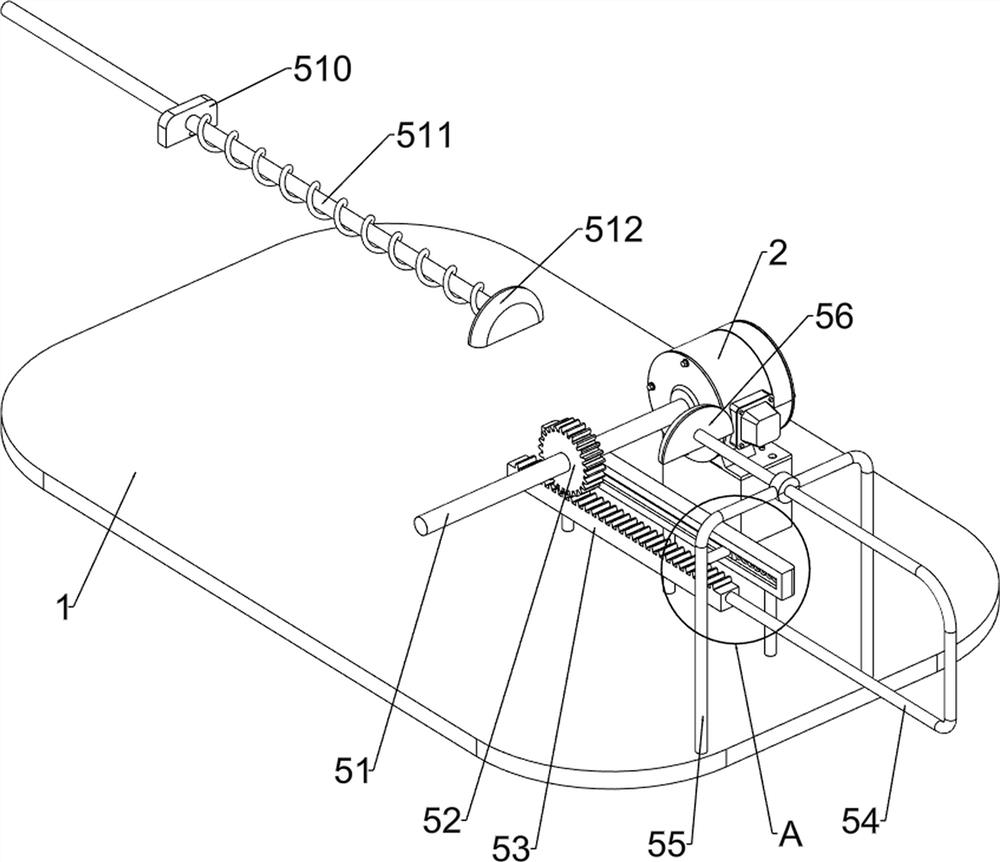
[0026] On the basis of Example 1, such as figure 2 , image 3 and Figure 4 As shown, the pusher mechanism 5 includes a first rotating shaft 51, a missing gear 52, a rack 53, a push rod 54, a first sliding sleeve 55, a first push plate 56, a first slide rail 57, a first telescopic assembly 58, The first slider 59, the first fixed plate 510, the second telescopic assembly 511 and the second push plate 512, the output shaft of the motor 2 is provided with a first rotating shaft 51, the first rotating shaft 51 is provided with a missing gear 52, and the first working The front side of the upper part of the table 1 is provided with a first sliding sleeve 55, the upper front side of the first workbench 1 is provided with a first slide rail 57, and the first slide rail 57 is slidably provided with a first slide block 59, and the first slide block 59 The first telescopic assembly 58 is connected between the first sliding rail 57, the left side of the first slider 59 is provided wi...

Embodiment 3

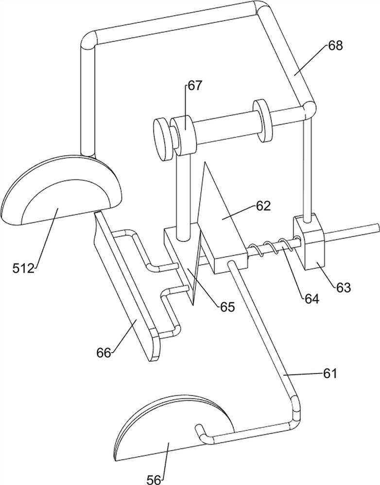
[0029] On the basis of Example 2, such as figure 1 , Figure 4 , Figure 5 and Figure 6 As shown, the pressing mechanism 6 includes a first connecting rod 61, a right wedge block 62, a second fixed plate 63, a third telescopic assembly 64, a left wedge block 65, a pressing plate 66, a second sliding sleeve 67 and a second connecting rod 68, the first connecting rod 61 is provided on the front side of the first push plate 56, the right wedge block 62 is provided on the rear side of the first connecting rod 61, the second connecting rod 68 is provided on the rear side of the second pushing plate 512, and the second connecting rod The upper part of 68 is slidingly provided with a second sliding sleeve 67, the bottom of the second sliding sleeve 67 is provided with a left wedge block 65, the left side of the left wedge block 65 is provided with a pressing plate 66, and the right side of the second workbench 3 is provided with a second fixed plate 63 , the second fixed plate 63...


PUM


Abstract

The invention relates to a slicing device, in particular to an automatic wood slicing device for building materials. According to the automatic wood slicing device for the building materials, the efficiency can be improved, the thickness of cut wood blocks can be adjusted, and convenience is achieved. The automatic wood slicing device for building materials comprises a first working table, a second working table, an electric saw, a pushing mechanism and a pressing mechanism. A motor is arranged on the side wall of the upper part of the first working table; the second working table is arrangedon the first working table; the electric saw is rotatably arranged on the second working table; the pushing mechanism is arranged on the first working table; and the pressing mechanism is arranged onthe second working table. The pressing mechanism can stabilize the wood block and prevent the wood block from being unevenly cut due to instability during cutting. After the wood blocks are sliced bythe electric saw, the wood chips can be collected by a collecting box and are convenient to arrange; and a distance adjusting mechanism enables the wood block to be cut thick or thin according to needs, the needs of people can be met, and convenience is achieved.

Description

technical field [0001] The invention relates to a slicing device, in particular to a wood automatic slicing device for building materials. Background technique [0002] The log is the length of the original strip cut into a certain length of wood according to the size, shape, quality standards or special regulations. This wood section is called a log. It has great uses in many fields such as papermaking and construction. , wood slicing is the most common, and traditional wood slicing is mostly a simple single-head design, which is relatively slow in operation, low in efficiency, and easy to be injured. [0003] Patent application CN208052133U, publication date 20181106, discloses an automatic slicing and polishing device for wood: it includes a base, one end of the base is fixedly connected to a cutting seat, the upper end of the cutting seat is fixedly connected to a fixed plate, and one side of the fixed plate is passed through a hydraulic cylinder. It is connected with a...

Claims


Application Information

Patent Timeline
IPC IPC(8): B27B5/06B27B5/22B27B5/29B27B25/00B27B27/02B27B27/10B27B29/02B27B31/08
CPCB27B5/06B27B5/222B27B5/29B27B25/00B27B29/02B27B27/02B27B27/10B27B31/08
Inventor 郭发友
Owner 蓝山县奔嘉木业有限公司
Why Eureka
Try Eureka