Wood machining device for cutting into circles

A technology for processing equipment and wood, which is applied to wood processing appliances, circular machines, manufacturing tools, etc., can solve problems such as inability to reduce dust, and achieve the effect of improving work efficiency

Inactive Publication Date: 2020-12-18
李宁
View PDF7 Cites 0 Cited by
  • Summary
  • Abstract
  • Description
  • Claims
  • Application Information

AI Technical Summary

Problems solved by technology

But it can't reduce the dust whi

Method used


Image

  • Wood machining device for cutting into circles
  • Wood machining device for cutting into circles
  • Wood machining device for cutting into circles

Examples


specific Embodiment approach 1

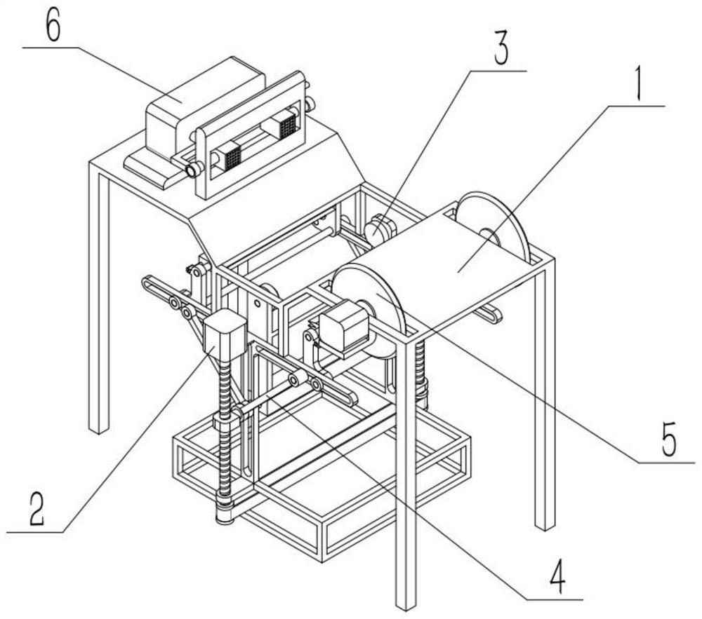
[0030] Such as Figure 1-8 As shown, a wood processing device that cuts into a circle includes a cutting frame 1, a power mechanism 2, a lifting mechanism 3, a cutting mechanism 4, a cutting mechanism 5 and a dust-reducing mechanism 6, and the power mechanism 2 is connected to the middle part of the cutting frame 1. At the lower end, the lifting mechanism 3 is connected to the middle part of the cutting frame 1. There are two cutting mechanisms 4. The two cutting mechanisms 4 are connected to the left and right ends of the cutting frame 1. The cutting mechanism 5 is arranged on the right end of the cutting frame 1. Cut the left end of frame 1.

specific Embodiment approach 2

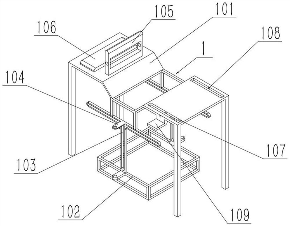
[0032] Such as Figure 1-8 As shown, a wood processing device that cuts into a circle, the cutting frame 1 includes a cutting frame 101, an underframe 102, a support rod 103, a convex seat 104, a rotating seat 105, a water tank seat 106, a strip groove 107 and a round hole 108, the front and rear ends of the lower end of the middle part of the cutting frame 101 are respectively fixedly connected to a support rod 103, the lower ends of the two support rods 103 are fixedly connected to the front and rear ends of the upper end of the chassis 102, and the upper and lower ends of each support rod 103 outer ends are fixed. Connect a convex seat 104, the rotating seat 105 is fixedly connected to the left end of the cutting frame 101 upper end, the water tank seat 106 is fixedly connected to the cutting frame 101 left end, the strip groove 107 is arranged on the front and rear sides of the cutting frame 101 right end, and the round hole 108 is arranged on Cutting rack 101 right side. ...

specific Embodiment approach 3

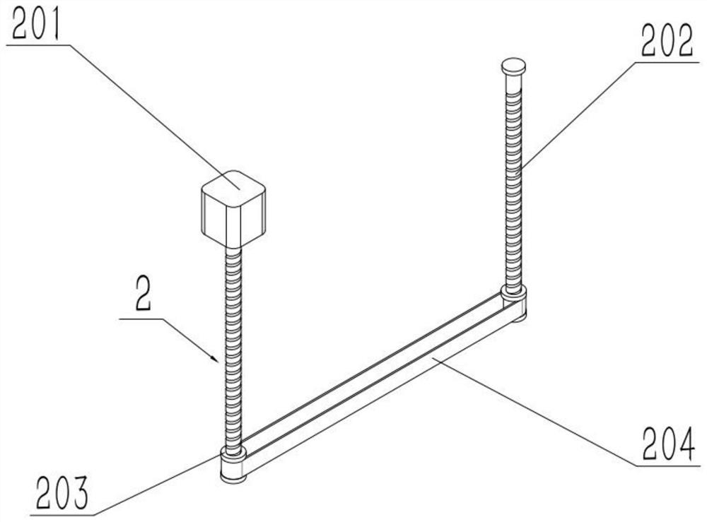
[0034] Such as Figure 1-8As shown, a wood processing device that is cut into a circle, the power mechanism 2 includes a first motor 201, a lead screw 202, a first pulley 203 and a first belt 204, and the lead screw 202 is provided with two, one lead screw The upper and lower ends of 202 are rotatably connected to the protruding seat 104 at the front end respectively, and the upper and lower ends of the other leading screw 202 are respectively rotatably connected to the protruding seat 104 at the rear end, and the lower end of each leading screw 202 is fixedly connected to a first One pulley 203, the two first pulleys 203 are connected through the transmission of the first belt 204, the output shaft of the first motor 201 is fixedly connected with the lead screw 202 at the rear end through a coupling, and the first motor 201 is fixedly connected at the upper end The upper end of the boss 104. When working, the first motor 201 is driven to drive the screw 202 at both ends to r...


PUM


Abstract

The invention relates to a wood machining device, in particular to a wood machining device for cutting into circles. The device comprises a cutting frame, a power mechanism, a lifting mechanism, two cutting mechanisms, a slicing mechanism and a dust falling mechanism. The power mechanism is connected to the lower end of the middle of the cutting frame. The lifting mechanism is connected to the middle of the cutting frame. The two cutting mechanisms are connected to the left end and the right ends of the cutting frame. The slicing mechanism is arranged at the right end of the cutting frame. Thedust falling mechanism is connected to the left end of the cutting frame. Wood can be cut into circles while the wood is cut at equal intervals. The wood which is long and not prone to being cut intocircles is cut at equal intervals through the slicing mechanism through manual operation, the wood with different lengths can be cut into circles conveniently, and the processed wood is the same in size, so that subsequent manual packaging, transportation and finish machining are facilitated.

Description

technical field [0001] The invention relates to a wood processing device, in particular to a wood processing device that cuts into circles. Background technique [0002] For example, Publication No. CN201821123982.3 A wood processing device that cuts into a circle. This utility model discloses a wood processing device that cuts into a circle, including a processing table, a fixed table and a dust collection tank. slide rail, and a telescopic rod is installed on the left side of the upper surface of the processing table, and a No. 1 motor is installed on the upper end of the telescopic rod, and a cutting knife is installed on the right side of the No. 1 motor. The block is connected with the fixed slide rail, and a rotating table is connected above the fixed table, the dust collection tank is located on the surface of the processing table, and the dust collection tank is connected with the fan through the air conveying pipe below, and the fixed slide rail There are fixing sc...

Claims


Application Information

Patent Timeline
IPC IPC(8): B27C9/04B27C5/00B27C5/08B27C5/06B27G3/00B01D47/06
CPCB01D47/06B27C5/006B27C5/06B27C5/08B27C9/04B27G3/00
Inventor 李宁
Owner 李宁
Why Eureka
Try Eureka