

Safety protection device for municipal engineering foundation pit
A safety protection device and engineering technology, applied in infrastructure engineering, transportation and packaging, excavation, etc., can solve problems such as foundation pit collapse, staff life safety hazards, etc., to achieve the effects of protecting safety, facilitating batch transportation, and improving efficiency
- Summary
- Abstract
- Description
- Claims
- Application Information
AI Technical Summary
Problems solved by technology
Method used
Image

Examples
Embodiment Construction
[0027] The following will clearly and completely describe the technical solutions in the embodiments of the present invention with reference to the accompanying drawings in the embodiments of the present invention. Obviously, the described embodiments are only some, not all, embodiments of the present invention. Based on the embodiments of the present invention, all other embodiments obtained by persons of ordinary skill in the art without making creative efforts belong to the protection scope of the present invention.
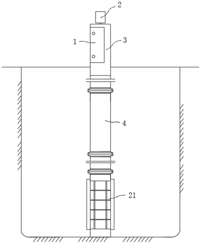
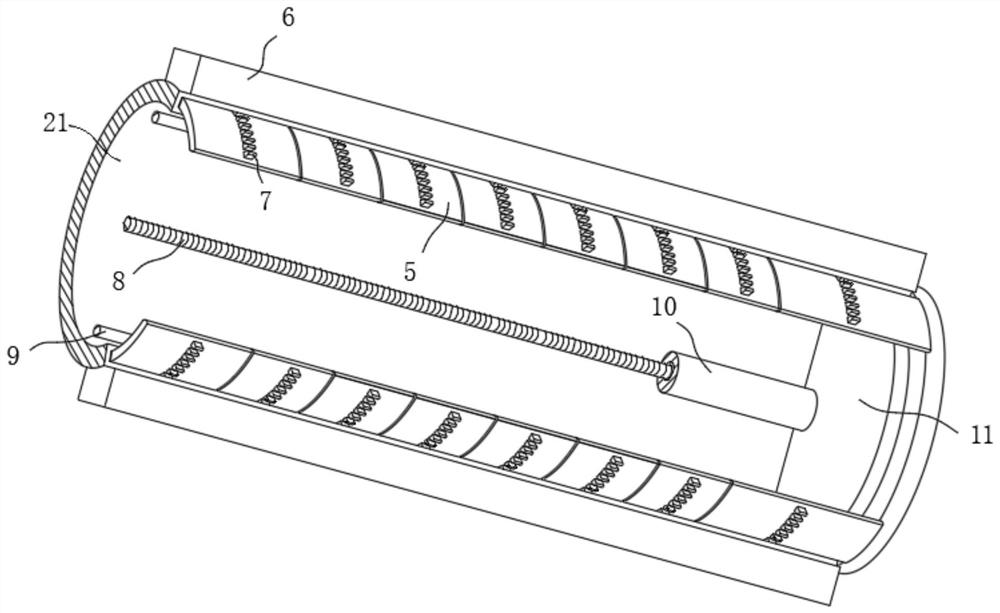
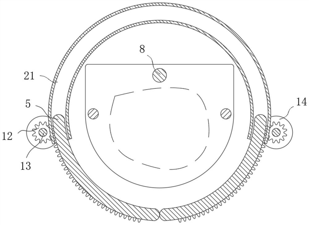
[0028] see Figure 1-3 , the present invention provides a technical solution: a municipal engineering foundation pit safety protection device, including a lower casing 21, characterized in that: the top of the lower casing 21 is fixed with several middle casings 4 by bolts, and the top of the middle casing 4 is fixed by bolts The upper casing 3 is fixed, and the top of the upper casing 3 is fixed with a lifting motor 2 by welding. The output shaft of the lifti...
PUM
 Abstract
Description
Claims
Application Information