Vertical streamline tunnel wheel supercharger

A technology of supercharger and tunnel wheel, which is used in non-variable-capacity pumps, machines/engines, components of pumping devices for elastic fluids, etc. problems, to achieve the effect of reducing losses, reducing possibilities and improving stability

Inactive Publication Date: 2020-12-18
科诺泰博(北京)科技有限公司
View PDF9 Cites 0 Cited by
  • Summary
  • Abstract
  • Description
  • Claims
  • Application Information

AI Technical Summary

Problems solved by technology

[0005] The support bearings of horizontal turbochargers are usually oil film bearings or rolling bearings. The mechanism for conveying lubricating oil needs to consume a certain amount of power, and the opened oil passage will also reduce the structural strength.
Moreover, with the miniaturization and high-speed development of turbochargers, ordinary bearings can no longer meet the speed requirements, and non-contact bearings have begun to be used, such as air bearings, while dynamic pressure air bearings do not require external air or oil supply. It uses The viscosity of the gas itself compresses the gas into the wedge-shaped gap through the rotation of the rotor to generate bearing pressure

Method used


Image

  • Vertical streamline tunnel wheel supercharger
  • Vertical streamline tunnel wheel supercharger

Examples


Embodiment 1

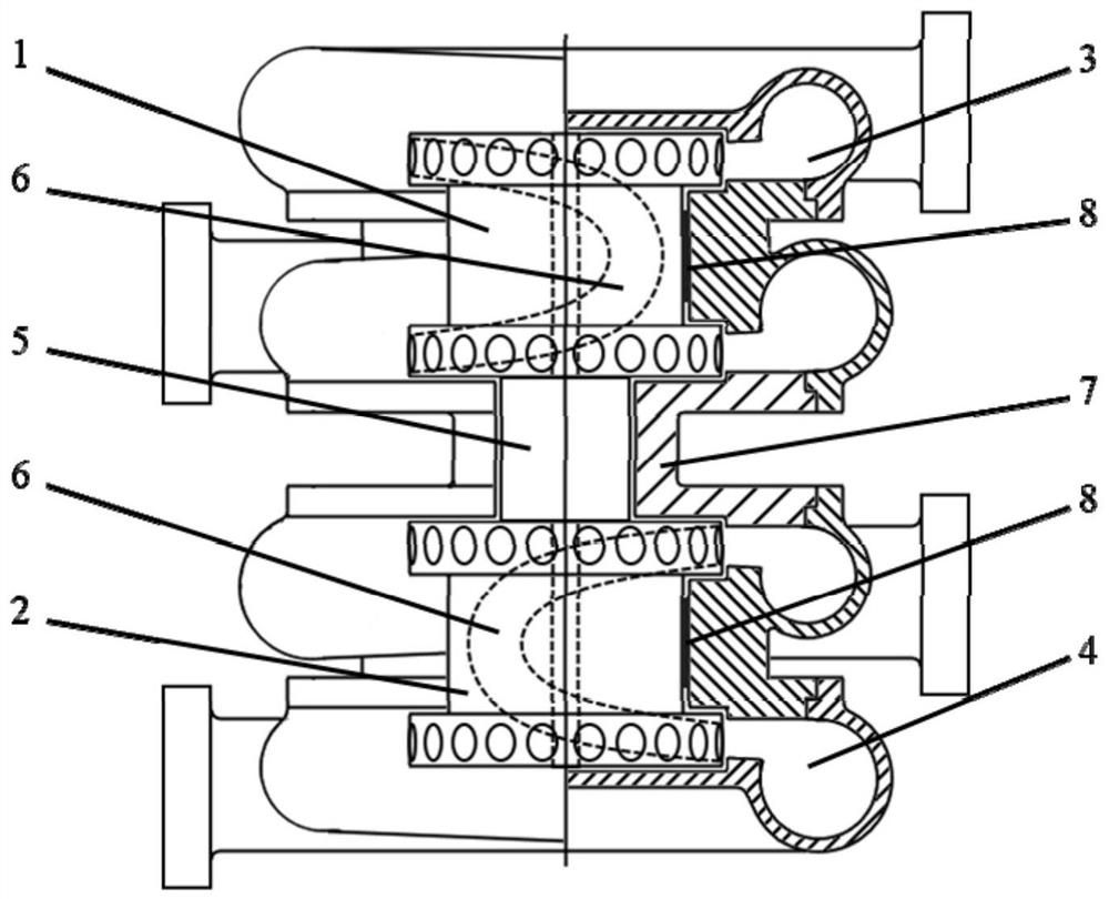
[0034]Such asfigure 1 As shown, the vertical streamline tunnel wheel supercharger, streamline tunnel compressor wheel 1, streamline tunnel turbine 2, compressor casing 3, turbine casing 4, and shaft 5; streamline tunnel compressor wheel 1 and The streamline tunnel turbine 2 is respectively installed at both ends of the rotating shaft 5 and forms a supercharger rotor; the rotating shaft 5 is arranged vertically and forms a vertical structure. In order to fix the turbocharger more stably, further, the rotating shaft 5 is arranged vertically and forms a vertical structure, which facilitates the use of a method of fixing the rotor at the upper and lower ends, which is more stable than a horizontal turbocharger. In order to form the streamline tunnel 6, further, the streamline tunnel compressor wheel 1 and the streamline tunnel turbine 2 are closed rotating mechanical structures, and the two structures can be completely the same; the streamline tunnel compressor wheel 1 and the streamlin...

Embodiment 2

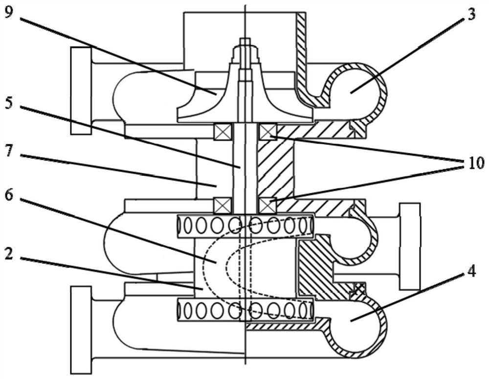
[0040]Such asfigure 2 As shown, with respect to Embodiment 1, in this embodiment, the supercharger rotor is composed of a vane compressor wheel 9 and a streamline tunnel turbine 2 installed at both ends of the rotating shaft 5.

[0041]Or the supercharger rotor is composed of a streamline tunnel compressor wheel 1 and a blade turbine. The streamline tunnel compressor wheel 1 and the blade turbine are installed at both ends of the rotating shaft 5.

[0042]The supporting bearings are ball bearings 10, which are respectively installed near the shaft diameters of the compressor end and the turbine end.

[0043]In summary, the vertical structure is adopted to avoid the influence of gravity on the rotor system and improve the stability of the bearing-rotor system; the turbine and compressor wheels adopt streamlined tunnel structures in structure. Compared with the blade structure, The structure of the turbine and the compressor wheel can be exactly the same, which can greatly reduce the design a...


PUM


Abstract

The invention discloses a vertical streamline tunnel wheel supercharger, and belongs to the field of turbochargers. The vertical streamline tunnel wheel supercharger comprises a streamline tunnel typeair compressor wheel, a streamline tunnel type turbine, an air compressor shell, a turbine shell and a rotating shaft, wherein the streamline tunnel type gas compressor wheel and the streamline tunnel type turbine are installed at the two ends of the rotating shaft correspondingly so that a supercharger rotor can be formed, the rotating shaft is vertically arranged and forms a vertical structure.According to the vertical streamline tunnel wheel supercharger, the streamline tunnel type turbine and the gas compressor wheel are adopted and matched with an external contour type air bearing to beinstalled in a vertical structure, and the beneficial effects of improving the rotating speed, improving reliability and stability, reducing leakage losses and reducing the size and the weight can beachieved.

Description

Technical field[0001]The invention relates to the field of turbochargers, in particular to a vertical streamlined tunnel wheel supercharger.Background technique[0002]The turbocharger can use the exhaust gas discharged from the engine to drive the turbine and drive the coaxial compressor to supercharge the intake air, increase the engine intake density, optimize vehicle power and economy, and reduce harmful gas emissions.[0003]Traditional open and semi-open blade structure impellers have tip clearances, and the number and thickness of the blades are limited by the level of material technology and there is no room for optimization, which limits the further improvement of the aerodynamic performance of turbines and compressors. At the same time, the tip clearance leakage flow not only affects the aerodynamic performance of the compressor and the turbine, but also affects the dynamic characteristics and reliability of the rotor; the structural strength of the thinner blade is poor, whic...

Claims


Application Information

Patent Timeline
Patent Type & Authority Applications(China)
IPC IPC(8): F02B37/00F01D5/04F01D25/24F01D25/00F01D25/16F04D29/28F04D29/42F04D29/02F04D29/057F04D29/059F04D29/056
CPCF01D5/048F01D25/005F01D25/16F01D25/166F01D25/24F02B37/00F04D29/023F04D29/056F04D29/057F04D29/059F04D29/284F04D29/4206Y02T10/12
Inventor 黄若郭文杰黄仕豪高泽
Owner 科诺泰博(北京)科技有限公司
Why Eureka
Try Eureka