Constant-pressure piston type particle damper

A particle damper and particle damping technology, applied in shock absorbers, shock absorbers, friction shock absorbers, etc., can solve the problems of single energy dissipation mechanism, non-recoverable energy, and low collision efficiency, so as to improve collision efficiency , Reduce time lag, reduce noise effect

Active Publication Date: 2020-12-18
TONGJI UNIV
View PDF11 Cites 1 Cited by
  • Summary
  • Abstract
  • Description
  • Claims
  • Application Information

AI Technical Summary

Problems solved by technology

[0004] The purpose of the present invention is to solve the problems of time lag, low collision efficiency, single energy dissipation mechanism and non-recoverable energy caused by the minimum limit of the acceleration threshold of the mass block displacement acceleration caused by the acceleration threshold when the particles collide in the traditional particle damper. Propose a Constant Pressure Piston Type Particle Damper

Method used


Image

  • Constant-pressure piston type particle damper
  • Constant-pressure piston type particle damper
  • Constant-pressure piston type particle damper

Examples


Embodiment Construction

[0035] The embodiments of the present invention are described in detail below. This embodiment is implemented on the premise of the technical solution of the present invention, and detailed implementation methods and specific operating procedures are provided, but the protection scope of the present invention is not limited to the following implementation example.

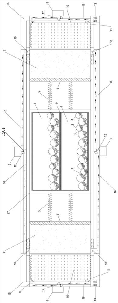
[0036] A controllable constant pressure piston type particle damper, the damper is fixed on the top of the structure to be damped, its structure is as follows figure 1 As shown, it includes a box 17 and a particle damping unit movable in the box 17. Both sides of the particle damping unit are symmetrically connected with baffles 6, and the particle damping unit and the inner side of the baffle 6 are connected by springs. 5 connection, the baffle can move along the inner wall of the box body 17, and an airtight storage chamber is formed between the outside of the baffle plate 6 and the box body 17, and liquid and / or...


PUM


Abstract

The invention relates to a controllable constant-pressure piston type particle damper which comprises a box body and a particle damping unit movably arranged in the box body, baffles are symmetricallyconnected to the two sides of the particle damping unit, and the particle damping unit is connected with the inner sides of the baffles through connecting springs. The baffles can move along the inner wall of the box body, and a closed storage cavity is formed between the outer side of each baffle and the box body. Liquid and/or gas are/is stored in the storage cavities, the storage cavities communicate with external pipelines, one-way valves are arranged in the pipelines, the pipelines are connected with turbines, and the turbines conduct energy recovery through the gas and/or the liquid exhausted by the storage cavities. According to the constant-pressure piston type particle damper, the problems of time lag, low collision efficiency, single energy dissipation mechanism, unrecoverable energy and the like caused by the minimum limitation of the acceleration threshold value on the displacement acceleration of a mass block when particles in a traditional particle damper are collided are solved.

Description

technical field [0001] The invention belongs to the field of vibration control of civil structures, and in particular relates to a constant pressure piston type particle damper. Background technique [0002] The particle damper is a passive control technology evolved from the traditional impact damper. Over the years, it has been deeply researched and applied in the fields of civil engineering, machinery, and aerospace. The particle damper is to fill a certain amount of particles in the limited closed space in the vibrating body or in the additional cavity outside the vibrating body, and use the friction and collision between the particles and between the particles and the wall of the cavity to consume the system. vibration energy, thus providing damping for the main structure and weakening the response of the main structure. Particle damping technology has the advantages of good durability, high reliability, insensitivity to temperature changes, good vibration damping perf...

Claims


Application Information

Patent Timeline
Patent Type & Authority Applications(China)
IPC IPC(8): F16F13/00F16F7/01F16F9/32F16F9/34F16F15/023F16F15/04F16F15/06
CPCF16F7/015F16F9/3207F16F9/34F16F13/007F16F15/023F16F15/046F16F15/06
Inventor 鲁正周超杰柳祥千
Owner TONGJI UNIV
Why Eureka
Try Eureka