Thermal power plant low-load denitration system based on fused salt energy storage system

A technology for thermal power plants and energy storage systems, applied in the field of energy storage, can solve the problems that the inlet flue gas temperature of the SCR denitration device cannot be guaranteed, the operation requirements of the SCR catalyst cannot be met, and the pollutant emission standards cannot be met.

Inactive Publication Date: 2020-12-18
CENT SOUTHERN CHINA ELECTRIC POWER DESIGN INST CHINA POWER ENG CONSULTING GROUP CORP
View PDF9 Cites 0 Cited by
  • Summary
  • Abstract
  • Description
  • Claims
  • Application Information

AI Technical Summary

Problems solved by technology

In the situation of deep transformation of thermal power units, ultra-low load (<40% of rated load) operation is required, but when ultra-low load is operated, the minimum load limit is limited by the flue gas temperature, and the flue gas temperature is too low to meet the operation requirements of the SCR catalyst
[0004] Although the current technical solution can achieve the purpose of deep peak regulation, when the unit is in deep peak regulation, the flue gas temperature at the inlet of the SCR denitrification device cannot be guaranteed, and the pollutant discharge standard cannot be met during low-load operation

Method used


Image

  • Thermal power plant low-load denitration system based on fused salt energy storage system

Examples


Embodiment Construction

[0015] Below in conjunction with accompanying drawing and specific embodiment the present invention is described in further detail, convenient to understand the present invention clearly, but they are not construed as limiting the present invention.

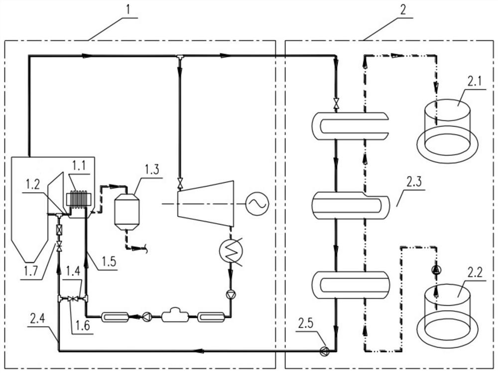
[0016] Such as figure 1 As shown, the present invention provides a low-load denitrification system for a thermal power plant based on a molten salt energy storage system. When the conventional thermal power generation system 1 is in deep peak-shaving and low-load operation, high-pressure steam enters the high-pressure steam molten salt energy storage system 2 for energy storage, which can reduce the steam intake of the steam turbine of the conventional thermal power generation system 1, thereby reducing power generation and realizing deep peak-shaving; After heat exchange between the high-pressure steam and the high-pressure steam molten salt energy storage system 2, it becomes high-pressure condensed water with a higher temperat...


PUM


Abstract

The invention provides a thermal power plant low-load denitration system based on a fused salt energy storage system. The thermal power plant low-load denitration system is characterized by comprisinga conventional thermal power generation system and a high-pressure steam fused salt energy storage system; an SCR technology is adopted for the conventional thermal power generation system for denitration; high-pressure steam generated by the conventional thermal power generation system is output to the high-pressure steam fused salt energy storage system through a pipeline; the high-pressure steam and the high-pressure steam fused salt energy storage system are subjected to heat exchange to form high-pressure condensed water, and the high-pressure condensed water is sent back to the conventional thermal power generation system through a high-pressure condensed water pipeline; the high-pressure condensed water pipeline communicates with an economizer water side outlet pipeline of the conventional thermal power generation system; and a bypass water supply pipeline of an economizer respectively communicates with the high-pressure condensed water pipeline and a conventional thermal powergeneration system water supply pipeline. According to the thermal power plant low-load denitration system based on the fused salt energy storage system, normal operation of the fused salt energy storage system and the denitration effect during low-load operation of a boiler are guaranteed.

Description

technical field [0001] The invention relates to the field of energy storage technology, in particular to a low-load denitrification system for a thermal power plant based on a molten salt energy storage system. Background technique [0002] In order to promote the grid-connected consumption of new energy power generation in my country, it is required to strengthen the peak-shaving capacity of the power system and comprehensively improve the peak-shaving of the system. One of the means is to increase the transformation of coal-fired power stations for peak-shaving and increase the peak-shaving of coal-fired power stations. Ability. The deep peak regulation of thermal power plants can help ensure the heating of thermal power units in winter, avoid the problem of abandoning wind and light, and enable my country to achieve the goal of adjusting the energy structure. [0003] At the same time, since the promulgation and implementation of the national "Emission Standards of Air Po...

Claims


Application Information

Patent Timeline
Patent Type & Authority Applications(China)
IPC IPC(8): F28D20/00F22D1/00F22D11/06
CPCF28D20/0034F22D1/003F22D11/06F28D2020/0047Y02E60/14
Inventor 祝培旺李峻王国贵秦鹏仇晓龙桂本张春琳
Owner CENT SOUTHERN CHINA ELECTRIC POWER DESIGN INST CHINA POWER ENG CONSULTING GROUP CORP
Why Eureka
Try Eureka