

Rotary kiln roasting structure and roasting process thereof
A rotary kiln and roasting technology is applied in the field of rotary kiln roasting structure and its roasting process, which can solve the problems of poor sand training, poor roasting effect, and inhomogeneous temperature, so as to improve the sand reduction degree and reduce the smelting cost. , the effect of reducing roasting energy consumption
- Summary
- Abstract
- Description
- Claims
- Application Information
AI Technical Summary
Problems solved by technology
Method used
Image

Examples
Embodiment 1
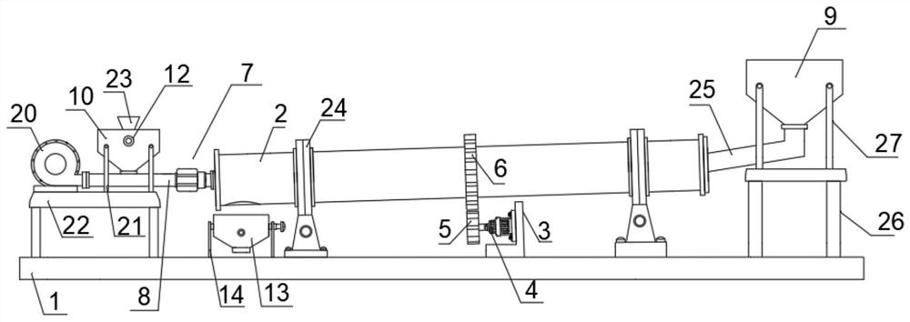
[0036] see figure 1 , Figure 3-5 , this embodiment provides a rotary kiln firing structure and firing process thereof, including a bottom plate 1, a rotary kiln body 2 is arranged above the bottom plate 1, a first motor 4 is arranged on the side below the rotary kiln body 2, and the first motor 4 The output end of the kiln is fixedly connected with the driving gear 5, the middle part of the rotary kiln body 2 is fixedly connected with the driven gear 6, the middle part of the upper end of the bottom plate 1 is fixedly connected with the fixed plate 3, and one side of the fixed plate 3 is fixedly connected with the first motor 4 through the fixed seat. The upper side of the driving gear 5 is meshed with the driven gear 6. First, the first motor 4 is turned on. When the output shaft of the first motor 4 rotates, the driving gear 5 is driven to rotate. Since the driving gear 5 and the driven gear 6 are meshed, the driven gear 5 is engaged. The gear 6 rotates, driving the rotary...
Embodiment 2
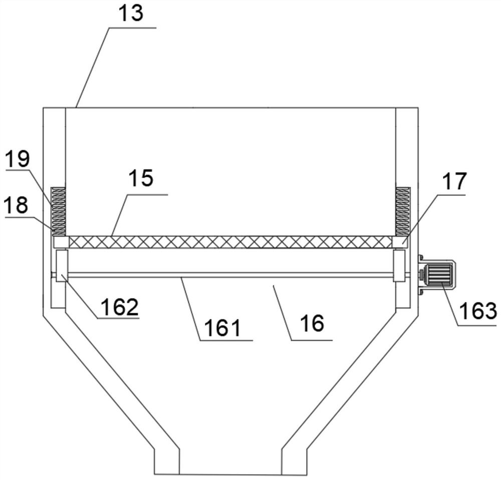
[0039] refer to figure 2 , Figure 6 , a further improvement made on the basis of Example 1:
[0040] A discharge hopper 13 is arranged below the end of the rotary kiln body 2 close to the burner 71. The rotary kiln body 2 is provided with a discharge hole relative to the discharge hopper 13. The material moves to the discharge hole of the rotary kiln body 2. The material hole falls, and the material falls into the lower relative discharge hopper 13. The middle part of the discharge hopper 13 is provided with a filter screen 15, and the four sides of the filter screen 15 are fixedly connected with side frames 17, and the material falls on the filter screen 15 in the discharge hopper 13. The filter screen 15 plays the role of screening, and the materials with qualified size are discharged through the filter screen 15, and the materials larger than the pores of the filter screen 15 are left on the filter screen 15. A vibration mechanism 16 is arranged below the filter screen 1...
PUM
 Abstract
Description
Claims
Application Information