Battery replacement locking device
A technology of electric locks and locking pins, applied in the direction of electric power devices, power devices, charging stations, etc., can solve the problems of easy failure, easy fatigue damage of bolts, easy shaking of batteries, etc., so as to improve installation reliability and avoid unsafe Reliability factor, effect of shortening replacement time
- Summary
- Abstract
- Description
- Claims
- Application Information
AI Technical Summary
Problems solved by technology
Method used
Image

Examples
Embodiment 1
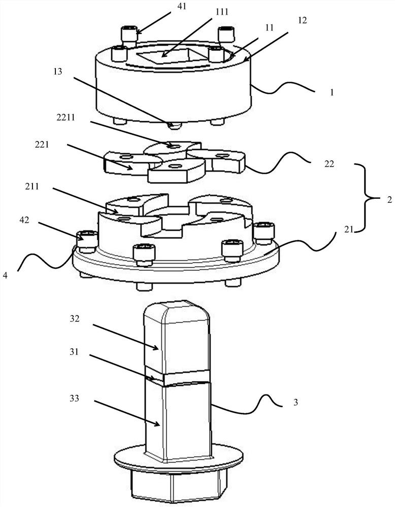
[0031] Such as figure 1 As shown, this embodiment provides a locking device for battery replacement, including a bearing assembly 1 , a flange assembly 2 , a square post bolt 3 and a fixing mechanism 4 .
[0032] Such as figure 1 As shown, the bearing assembly 1 includes an inner steel ring 11, an outer steel ring 12 and a locking pin 13, the inner steel ring 11 is arranged inside the outer steel ring 12, and the middle of the inner steel ring 11 is provided with A bearing hole 111 , the bearing hole 111 is square, and the bearing hole 111 is used to accommodate the square column bolt 3 , and the locking pin 13 is arranged at one end of the inner steel ring 11 .
[0033] Such as figure 1 As shown, the flange assembly 2 includes a flange 21 and a stop piece 22, the surface of the flange 21 is provided with a mounting groove 211, the stop piece 22 is located in the installation groove 211, the The stop piece 22 is provided with several blades 221 , and the blades 221 engage w...
Embodiment 2
[0042] Such as figure 1 As shown, this embodiment provides a locking device for battery replacement, including a bearing assembly 1 , a flange assembly 2 , a square post bolt 3 and a fixing mechanism 4 .
[0043] Such as figure 1 As shown, the bearing assembly 1 includes an inner steel ring 11, an outer steel ring 12 and a locking pin 13, the inner steel ring 11 is arranged inside the outer steel ring 12, and the middle of the inner steel ring 11 is provided with A bearing hole 111 , the bearing hole 111 is square, and the bearing hole 111 is used to accommodate the square column bolt 3 , and the locking pin 13 is arranged at one end of the inner steel ring 11 .
[0044] Such as figure 1 As shown, the flange assembly 2 includes a flange 21 and a stop piece 22, the surface of the flange 21 is provided with a mounting groove 211, the stop piece 22 is located in the installation groove 211, the The stop piece 22 is provided with several blades 221 , and the blades 221 engage w...
Embodiment 3
[0054] This embodiment provides an automobile, which includes a battery pack bracket, a vehicle body floor, and the above-mentioned battery replacement locking device, and the battery replacement locking device includes a bearing assembly 1, a flange assembly 2, a square post bolt 3 and a fixing Institution 4.
[0055] Specifically, the bearing assembly 1 includes an inner steel ring 11, an outer steel ring 12 and a locking pin 13, the inner steel ring 11 is arranged inside the outer steel ring 12, and the middle of the inner steel ring 11 is provided with A bearing hole 111 , the bearing hole 111 is square, and the bearing hole 111 is used to accommodate the square column bolt 3 , and the locking pin 13 is arranged at one end of the inner steel ring 11 .
[0056] Specifically, the flange assembly 2 includes a flange 21 and a stop piece 22, the surface of the flange 21 is provided with a mounting groove 211, the stop piece 22 is located in the installation groove 211, the The...
PUM
 Abstract
Description
Claims
Application Information
 - Generate Ideas
- Intellectual Property
- Life Sciences
- Materials
- Tech Scout
- Unparalleled Data Quality
- Higher Quality Content
- 60% Fewer Hallucinations
Browse by: Latest US Patents, China's latest patents, Technical Efficacy Thesaurus, Application Domain, Technology Topic, Popular Technical Reports.
© 2025 PatSnap. All rights reserved.Legal|Privacy policy|Modern Slavery Act Transparency Statement|Sitemap|About US| Contact US: help@patsnap.com